
State-of-the-Art on Technological Developments and Adaptability of Prefabricated Industrial Steel Buildings

1
School of Civil Engineering, Tianjin University, Tianjin 300072, China
2
State Key Laboratory of Hydraulic Engineering Simulation and Safety, Tianjin University, Tianjin 300072, China
3
Key Laboratory of Coast Civil Structure Safety, Ministry of Education, Tianjin University, Tianjin 300072, China
4
College of Agriculture, Guizhou University, Guizhou, Guiyang 550025, China
5
Faculty of Mountain Agriculture and Environmental Sciences, Kohsar University Murree, Murree 47150, Pakistan
*
Authors to whom correspondence should be addressed.
Appl. Sci. 2023, 13(2), 685; https://doi.org/10.3390/app13020685
Submission received: 1 December 2022
/
Revised: 21 December 2022
/
Accepted: 28 December 2022
/
Published: 4 January 2023
(This article belongs to the Special Issue Seismic Response and Damage Analysis of Geotechnical Engineering Structures)
Abstract
:Compared to traditional onsite steel construction, prefabricated industrial steel construction (PFISC) saves time, money, and resources. It results in sustainable steel structures that use fewer resources and are better for the environment. Despite their advantages, the private sector favors creating high-rise buildings in an old-fashioned way. In order to encourage the adaptability of prefabricated industrial steel buildings (PFISBs) in high-rise structures, this study critically evaluates the adaptable solutions offered in the literature on the recent developments, structural performances, present difficulties, and future potential. In mid-rise and low-rise structures, PFISC is frequently used. In research and case studies, PFISBs have proven to perform admirably under various adverse conditions, including in the event of an earthquake, wind, blast, impact, fire, collapse, and long-term sustained loads. The use of potential research solutions, the “Top-down” strategy, and the resolving of problems such as the structural-based design guidelines, column stability, discontinuous vertical and horizontal diaphragms, cluster columns and beams effect, damage-free and innovative inter- and intra-modular connections, high strength-to-weight modules, numerical simulation, and transportation will help PFISBs to become more widely accepted in high-rise structures. Compared to other materials, steel has recently demonstrated great promise for the construction of PFISBs. Additionally, China plans to increase their PFISC to 30% by 2026, Australia to 15% by 2025, and North America to over 5% by 2023, proving that it is a reasonable response to future urbanization concerns.
Keywords:
prefabricated industrial steel buildings; automated and detachable IMCs; vertical and horizontal diaphragm continuity IMCs; foundation fixity systems; seismic and wind-resistant systems; explosion; collapse; vibration; fire-resistant systems; column–column and column–beam joints damage issues1. Introduction
Compared to traditional construction, prefabricated industrial construction (PFIC) has recently increased in its importance for modern urbanization. This is because of energy consumption, global expectations, green building, and outstanding structural performance [1,2,3]. It has relied on the industrialization of parts or finished rooms transported and installed using simple connections, as shown in Figure 1 [4,5,6,7,8]. It is widely used in emergencies and repetitive construction projects, such as dwellings, military housing, dorms, clinics, and classrooms [9,10,11]. This has already been introduced in China, the United Kingdom, Japan, Korea, Australia, Germany, the Netherlands, and the United States [1,11,12,13,14,15,16,17]. The UK’s housing industry attempted to accommodate 25% of housing societies, and China’s central and regional governments considered 30–50% with a 2–3% annual increase until 2026 [1,18]. This is sufficient evidence that PFIC is more efficient than the conventional techniques and is essential to meet the housing demand.
Materials used in PFIC are usually the same as onsite construction, but the components are manufactured under regulated conditions, resulting in better quality industrial modular units (IMUs). However, lightweight materials are always preferred for easy handling, assembly, and transport. Among the materials used in PFIC are steel, concrete, timber, and aluminum. Although aluminum IMUs are lighter, 1.5 times stronger, and have tighter tolerances than steel IMUs, their brittleness and high price remain significant barriers [19]. Timber is often used in low-rise PFIC, whereas steel and concrete have historically been the standard for high-rise PFIC. Steel is preferred over concrete since it is 25–30% lighter, more resilient, and requires fewer joints [20]. Timber necessitates polishing onsite, while concrete demands an accessible base to minimize the self-weight. On the other hand, steel is robust and stiff enough not to be oversized or downsized to obtain prefabricated industrial steel buildings (PFISBs). This inherent strength enables IMUs to withstand oscillations during shipping without requiring support, resulting in reduced transport costs compared to other conventional materials [6]. Including its inherent strength, steel’s structural stability, notably its strength against dynamic loads, increases its preference as a material in high-rise PFISBs, revealing itself to be more affordable than concrete structures. Thus, steel is a favored material choice among architects for high-rise PFISBs [21].
Prefabricated industrial construction displayed an exceptional quality, efficiency, productivity, and versatility. It proved to have shorter project durations, lower overall costs, and the less wastefulness of resources [22]. Therefore, it possesses the potential of a sustainable construction method [23]. Lawson et al. [24] reported an improved sustainability by reducing the construction waste from 10–15%, site visits to 70%, site disruption or noise pollution from 30–50%, and onsite accidents above 80%. Additionally, it was found to lower the environmental impacts by reducing the material wastage to 64%, greenhouse gas emissions to 40% [25], and economic implications by reducing the production hours to 31% [26]. A comparative study concludes that a reduction in the economic impact can be achieved by saving 60% of steel, 77% of the framework [27], and reducing the resource depletion to 36%, a social influence by limiting the health damage to 6.6%, the environmental impact by reducing the ecosystem damage to 3.5%, and economic implications by the reduction in the energy consumption to 20% [28]. It can be concluded that PFIC can increase the productivity, efficiency, and safety while decreasing the number of onsite visits, transport activities, material wastage, noise pollution, energy consumption, hazardous gas emissions, and reliance on unskilled labor. The critical advantage originates from its quick fabrication; this can reduce the construction time by 30–50% compared to conventional construction. In China, broad sustainable building (BSB) was pioneered with the T30 tower [29] in 15 days and the J57 tower [30] in 19 days. The 60-story Collins house, 44-story Atira student accommodation, and La Trobe towers in Australia are the tallest panelized PFISB skyscrapers [31]. The 44-story Croydon tower [32], 32-story B2 tower [33], 29-story Apex [34], and SOHO tower [35] are high-rise volumetric PFISB skyscrapers using PFIC. By developing the two fastest temporary hospitals, i.e., Huoshenshan and Leishenshan, within 6–10 days in Wuhan, China, the PFIC method has fully achieved its goal of being an environmentally friendly, speedy, and dynamic form of construction [36,37].
The review is primarily concerned with researching the comparatively most adaptable recent technological advancements, structural measures, and stability systems, or research solutions in terms of the sustainability, workability, and performance in the event of an earthquake, wind, fire, blast, vibrations, and progressive collapse to meet the design and safety requirements. Furthermore, this study lists the limitations of these technologies. It introduces some solutions or opportunities that should be investigated to address all of the technical issues not addressed in previously developed solutions to improve the adaptability of PFISB in high-rise buildings. It is because, due to the strict requirements set forth by the construction industry, PFISC is only used in a few high-rise PFISB projects, despite its many benefits. This is due to unfamiliarity with or lacking detailed and comprehensive content on the most recent and relevant technological and research advancements with new potential research solutions [33,38,39,40,41]. The study investigated that upon resolving the above-noticed technical challenges, the adaptability of PFISBs in high-rise PFISC applications can be increased [42]. As a result, the present study will look at (i) the recent technological developments and their structural performances, (ii) the limitations and technical challenges and constraints offered by these advancements, and (iii) the potential future research solutions, measures, and opportunities to address these technical issues. This paper analyzes and thoroughly researches contemporary breakthroughs in the structures of PFISBs, the structural performances, difficulties, and growth expectations. The study’s findings are intended to encourage the expansion of PFISC as a resource for professionals, academics, and specialists.
2. Background of the Study
Many synonymous terminologies are used to characterize PFISBs, but they are often misunderstood. Prefabricated industrial steel construction, for example, is the method of forming and assembling a specified number of building components before shipping and installing them onsite. Modular construction, or modularization, on the other hand, is a form of PFISC that describes the process of designing and fabricating volumetric buildings, or “industrial modular units (IMU)/modules”, in a factory and transporting them to the worksite for an onsite assemblage. The terms “amount of prefabrication”, "penalization”, and “modularization” are used interchangeably [43]. This article focuses on a modularized PFISB that is commonly investigated. This research looks at PFISC and PFISB as construction approaches that use technology to advance the process from the initiation to its implementation. The designing, manufacturing, shipping, assembling, reliability, and connectivity of structural systems and buildings are all addressed in this approach.
3. Research Methodology
The systematic review and screening process used in the article is thorough, starting with a broad search for publications using general keywords and moving on to a step-by-step exclusion of studies that did not pertain to the research topic. Significant research, inventions, articles, and case studies are obtained for various relatively broad search results through a filtering process, primarily from English, Chinese, Korean, and Japanese. The scope of the study area is determined by looking at the keywords and summary of each article. Improvements in PFISBs and IMUs are one example. Then, works of literature outside of the scope were excluded, including those about material testing and PFIC using concrete or timber IMUs. Only studies that directly applied and validated scientific advancements in 3D PFISBs are included.
3.1. Keywords
Many other keywords were used for searching besides the study’s main keywords, such as prefabricated industrial construction (PFIC), prefabricated industrial steel buildings (PFISBs), and industrial modular units (IMUs). Prefabricated prefinished volumetric construction (PPVC), prefabricated modular construction (PMC), prefabricated construction (PC), permanent modular construction (PMC), container housing, container structures, modular integrated construction (MiC), offsite construction (OC), offsite construction technique (OCT), manufactured construction, industrialized building system (IBS), modular steel building (MSB), modular steel structure (MSS), modular construction (MC), modular steel construction (MSC), industrialized construction (IC), manufactured housing, industrialized building, and prefabrication has been shown to be the most successful method for locating publications about industrialized building.
3.2. Sources and Databases
A selection of scholarly databases, including the Web of Science, Google Scholar, Science Direct, Scopus, Wiley, Springer, academia, and researchgate, were picked for an extensive investigation of journal articles and conference proceedings. Chinese theses, patents, and papers were located using the CNKI database, and Korean research was found using Korean science. Additionally, some English and Chinese patents were downloaded using Google Patents.
4. Technological Advancements
4.1. 2D to 3D Assembling Techniques
Prefabricated industrial steel constructions have become increasingly popular recently. They are used in the construction of low-rise structures as well as high-rise PFISB skyscrapers. A Hickory Building System (HBS), consisting of panelized systems to build PFISBs, such as load-bearing walls, concrete floors, and facades, involves integrating and assembling 2D panels onsite to form 3D IMUs through wet joints. The 44-story Atira student accommodation, 60-story Collins house, and 44-story La Trobe towers in Australia used HBS technology [31]. With 80–95% factory-based fabrication, 3D IMUs can be recognized as mobile homes [44]. The 44-story Croydon tower [32], 32-story B2 tower [33], 29-story Apex [34], and SOHO tower [35] used the completely finished 3D IMU. Before moving to the site, the 3D IMU is always fully serviced and prefinished in the factory. HBS systems, on the other hand, are less sustainable because they require an onsite finish and assembly, increasing the complexity and onsite working, reducing the construction productivity. However, compared to traditional steel construction, both panelized and volumetric PFISBs could reduce the construction time by more than 30–50%.
4.2. Industrial Modular Units Forms
Prefabricated industrial steel buildings are classified as continuous and corner-supported [45,46]. Walls which guard continuous supported PFISBs, such as lightweight walls and a hybrid module–barrel system, are developed. The sides of the lightweight wall PFISB are supported by light C-section members that are only suitable for low-rise structures [47,48]. Since they are composed of SHS and can withstand vertical and lateral stresses, the PFISB module–barrel hybrid system, on the other hand, can be employed in high-rise structures [45,47,48,49]. Corner columns in corner-supported PFISB structures principally resist the load. Light and heavy steel IMUs are the corner-supported PFISB. ATLS is a lightweight PFISB that can be built and dismantled multiple times using open, thin-walled, cold-formed sections. They are favored in low-rise structures since their weak connection leads to a minimal structural integrity [50]. SHS columns welded with SHS beams support heavy steel IMUs. Such IMUs are utilized in high-rise PFISBs because of the high bending resistance, lateral–torsional, torsional, and compression of the columns and beams [51,52]. In conclusion, continuous supported module–barrel hybrid PFISB has increased the in-plane rigidity and lateral stability [53]. They have an excellent lateral and longitudinal stability compared to heavyweight corner-supported PFISBs due to load sharing across several columns, making them better suited for high-rise PFISBs [45].
4.3. Manual to Automatic Non-Detachable Inter-Modular Connections
For manually operating PFISBs, inter-modular connections (IMCs) that are welded, bolted, and prestressed are frequently used, as shown in Figure 2a–f. While all of these IMCs have been demonstrated to have an adequate seismic resistance in pertinent investigations, they do have challenges. Due to the extensive onsite work of the welded IMCs, there is not enough room for MEP services, a secure weld quality, and full welding [54]. Welded connections were the most common type of IMC studied by Annan et al. [10,54,55,56] that exhibited a satisfactory performance; nevertheless, they are costly, of a poor quality, and require functional space for internal connection welding [57]. As depicted in Figure 2a, welding connections are avoided due to the aforementioned difficulties; hence, bolted connections are chosen on the construction site [38,54]. Bolted IMCs have strict operational space requirements and a lower production efficiency [58]. Doh et al. [59] discovered that bolted bracket connections were susceptible to prying failure, exhibiting a brittle behavior and are suited for low-rise structures. Thus, Chen et al. [60,61] developed rotary connectors that protect the columns; access holes are used for large bolt tightening, as displayed in Figure 2b [62]. The experiments demonstrated an outstanding bearing capacity and ductility in high-rise PFISB extreme dynamic situations [63]. Plug-in supported joints are developed which can fully assemble interior IMUs, and their seismic performance has been studied, such as the beam and column bolted IMC in Figure 2d [64]; fully bolted IMC in Figure 2e [65]; and beam bolted IMC in Figure 2c [66,67]. They demonstrated a superior ductility, energy dissipation, plastic deformation, and bearing capacity, whereas the weld of the intra-modular joint fractured; nonetheless, the failure was transmitted to the column. The building regulations for the prestressed IMC are stricter and more complicated. Prestressed rebars can join columns vertically, but their limited moment-resistance capability makes them unsuitable for high-rise buildings because superimposed forces can cause elevating and joint failure [40]. In order to achieve the composite prestressed joint shown in Figure 2f, the columns are filled with concrete. This joint effectively transfers medium-level lateral forces in a ductile manner due to the contact bond between the concrete, plug-in, strands, and shear bloc; however, a significant bond reduction can cause concrete crushing, a gap formation, strength, and stiffness degradation [68,69]. Workers may also bolt or weld the corners and exterior interface from the outside. The IMUs’ wall panels and slabs, particularly the installation, do not have the necessary construction clearance for the internal IMC. Some IMCs do not make the final IMU tighter. Others, on the other hand, prefer to make holes in order to assemble them, which may compromise the IMUs’ sectional integrity and interior design. In order to address the problems above, various automatic IMCs that require no functioning space have recently been developed, as shown in Figure 3a–g. The researchers designed a sliding bloc IMC that joins the IMU via a self-locking setup, as shown in Figure 3a [57]. The joining method resembles the lock-tongue joint in Figure 3f in appearance [70]. Another investigation also created the self-locking slider joint displayed in Figure 3e which works similarly with the joins in Figure 3a,f [71]. The top movable panel and springs are attached to the side of the bottom IMU column, and the plug is attached to the base of the upper IMU column. As a result, the connector is fixed, the slider panels move laterally during the mounting of the IMU, and a slip forms between the top and bottom segments of the plug. Self-locking connections’ hysteresis behavior featured plumper hysteretic rings and worked well in seismic tests. Since their initial stiffnesses were comparable to those of the welding connection, they were just as dependable as the welding IMC. The problem with these connections was that they only fixed two sides by locking sliders on two sides, leaving the other sides loose or unsupported, which made them weaker in earthquake-prone areas. Therefore, to achieve the fixity of the tubes and IMC in opposite and neighboring four sides, researchers developed pin-type joints, as shown in Figure 3c [72], and plug-in type joints, as shown in Figure 3d [73], inserted inside columns, which further improved their seismic performance and made them suitable for mid- to high-rise PFISBs. Other researchers, such as Dai et al. [74] and Picard [75], depicted in Figure 3b,g, built an installation-friendly self-locking fastener machine by using springs and nuts and bolts to provide support around the bolt shaft. Their seismic performance shows that they behave as semi-rigid to rigid in high-seismic zones, making them suitable for usage in high-rise PFISBs. However, these self-locking IMCs ignore construction or deformation tolerances, which require a high degree of precision. Additionally, these IMCs cannot be removed once locked, making it challenging to reuse the IMU in the event of accidental damage during servicing.
4.4. Manual to Automatic Detachable Inter-Modular Connections
Inter-modular connections cannot be removed once locked, making it challenging to reuse the IMU in the event of accidental damage during servicing. Because of this issue, researchers created bolted and pin types of IMCs through SHS, as shown in Figure 4a–d. They consider the constructional tolerance brought on by the automatic mechanical IMC and the repetitive use of IMUs via a replaceable or detachable IMC. The threaded block of the lower IMU is tightened to the bolt of the upper IMU using a long twisted rod that the authors designed for the detachable IMC shown in Figure 4a [70] and pinned joint shown in Figure 4d [76]. Although these joints are detachable, tightening the bolts inside the columns requires a lengthy rod tool, which is laborious; hence, the bolt diameter or screwing length is typically small, reducing their seismic and lifting capacities. Consequently, as shown in Figure 4b, a mechanical replacement has recently been developed to address these difficulties. A new, low-carbon mechanical IMC integrates the IMU horizontally and vertically through linearly translating the pins and transfer plates. An extended twisting rod is used in this connection to operate the mechanical arrangement of the components and pin them together [77,78]. As soon as the bolt is turned, horizontal pins instantly lock into place and establish a solid connection between the IMUs on the exterior and interior. These joints perform reliably in seismic and pullout operations. Because these bolted joints are only helpful in tightening or demounting corner and hollow columns, researchers created a new way to connect the beams rather than the columns without the need for any tightening equipment, as depicted in Figure 4c. The onsite fastening connections are replaced by a robust mechanical interconnecting system that allows for twist, tilt, and slide adjustments [79]. However, the joining system cannot withstand the tensile stresses, which forces the use of pricey adhesives and causes the uplift under extremely high lateral loads.
4.5. Lateral Loads Stabilizing Systems
Lateral stability systems are developed, including braces, shear walls, diaphragm walls, cores, base isolators, and viscoelastic dampers to resist the effect of lateral forces on high-rise PFISBs due to the incapability of the IMCs. As seen in Figure 5a–d and Figure 6a–f, IMCs have recently been invented. According to Sultana et al., superelastic self-centering SMA bracing and SMA bolts’ IMC minimizes the residual stresses and is a recyclable solution [80,81]. Through self-centering, the haunch bracing system proposed in Figure 6c improved the IMCs’ ductility [65]. Recently, a slider device with reusable bonded rubber units was devised [82,83,84,85,86]. After 5 mm of torsion and translation, they may dissipate 80% of the earthquake energy through friction. The haunch bracing with a plug-in IMC transferred the failure from the joints to the beams and demonstrated superior self-centering systems that may be used in high seismic zones for mid- to high-rise PFISBs. Moreover, the PFISBs’ and system’s full strength can be achieved using a double-skin steel shear wall, as shown in Figure 6b [87]. The composite action of the Corefast 2D and 3D walls increases the fire resistance while attempting to prevent the lateral force damage, as shown in Figure 6f [6]. This is a functional lateral force-resisting system because it delays the structure’s yield, increases the elastic stiffness with a yielding wall panel, and prevents out-of-plane buckling prematurely while causing column tearing and strength degradation due to local buckling [87]. However, the lateral stability offered by these stabilizing systems is limited because the upper and lower IMUs’ interconnectivity is lacking in regions other than the column corners. As per evaluation, the linked wall systems made up of numerous vertical bars and sleeves could aid structures with the superior lateral response, as shown in Figure 6d [88] and Figure 6e [89]. They rigidly connect vertical diaphragms using a composite connection between the walls using bars. Recently, one of the authors patented a base isolation technology, as shown in Figure 6a [90]. This satisfies the requirements for the standard use, structural bearing capacity, and an effective resistance to the effects of earthquakes. However, they are suitable for pre-tensioned and composite types of IMCs inside the columns of PFISBs. Therefore, other energy dissipation joints are developed; for instance, the authors invented a rubber isolation system [91] and a self-locking tenon-and-mortise vibration isolation rubber IMC in the IMU, as shown in Figure 5a,b [92]. The invention may reduce the adverse effects of earthquakes and improve the PFISB structure’s bearing capacity. Similarly, two distinct configurations of bolted IMCs having washer and resilient rubber layers are demonstrated, as shown in Figure 5d [93]. It has been shown that the IMCs which have been bolted are rigid and cause a column fracture, as opposed to the IMC in Figure 5d, which has been strengthened with resilient layers which can withstand significant deformations without fracturing the bolt [93]. A lead viscoelastic damper in a vertical IMC dissipated more energy than the conventional bolted IMC, such as those shown in Figure 3a–f and Figure 4a–d [94]. The damping joints in Figure 5a–d have the effect of delaying the premature failure of the structural components. They prevent a failure and collapse, increase the capacity, and guarantee security.
4.6. Top-Down Assembling Approach
The recently developed “Top-Down approach” involves building a structure from the top floor to the first floor [95]. The structural frame was designed with a hydraulic jack lifting system, eliminating the need for large cranes. The system can elevate the PFISBs’ structure while supporting the horizontal loads, minimizing swaying, and ensuring the structure’s integrity. Furthermore, it eliminates the need for scaffolding and cranes when operating at a height, improving the worker safety and reducing the time and labor expenses. The advantages include unloading, directly inserting the IMUs from the truck into the frame, and permitting working space around the cluster columns at the base. According to the frame type, this could be classified as essential or extended systems [96]. The frame is packed with a steel IMU created individually. Through the use of peripheral moment-frames, the lateral stability is enhanced.
4.7. Vertical and Horizontal Diaphragm Continuity Systems
There were significant problems with the PFISBs’ in-plane stiffness and non-uniform lateral force transmission because of the discontinuity between the floor and wall diaphragms and no adequate connection system developed on the beams. In order to address the issues mentioned earlier, the authors most recently created a horizontal IMC using the tongues and grooves between the beams, as shown in Figure 7a [92]. Sharafi et al. [79] also designed a horizontal and vertical beam IMC that resists shear forces and provides a diaphragm continuity in both horizontal and vertical directions, as shown in Figure 7c. Both methods required expensive adhesives or a corner column–column IMC to fix because they could not withstand the uplift stresses. In order to offer horizontal and vertical diaphragm connectivity and an adequate lateral force resistance, the recent developments in the IMC, such as the wall-to-wall vertical shown in Figure 7d [97] and diaphragm-to-diaphragm horizontal IMC shown in Figure 7e [98], have been made. They had a sustainability challenge because extensive site work would be required. In order to accomplish a connection at diverse locations, another sustainable approach has been devised that uses field bolts to attach the IMU horizontally and vertically by welding angles to the beam flanges in both directions, as illustrated in Figure 7b [99].
4.8. Automated and Robotized Systems
Due to the congested gaps between IMUs, fully finished 3D IMU-fitted PFISBs have difficulties installing MEP facilities. A single 3D file combining architectural, structural, and MEP data allowed for the effective implementation of the BIM to visualize and identify hundreds of conflicts between MEP and structural systems [100]. Additionally, to lessen the IMUs and component damage during transit, both structural and nonstructural. The conveyance of IMUs is planned, optimized, and visualized using the integrated BIM platform, Geographic Information System (GIS), and Vehicle Routing Problem (VRP) [101]. The system was discovered to track the environment, the network of roads, and the best route for the safe transfer of IMUs. The traditional manual techniques for configuring, choosing, and positioning the cranes remained dangerous; as a result, the Hevilift automated crane planning and optimization approach to effectively deploy thousands of cranes simultaneously has recently been implemented [102]. The robotized crane assembly with automation allowed the IMUs to be hoisted and installed with outstanding autopilot precision and safety, greatly enhancing the safety and sustainability of PFISBs [103].
4.9. Foundation Fixity Systems
Due to the close proximity of the four columns in the PFISBs, they are more prone to sliding and overturning when subjected to high lateral loads; as a result, an adequate restraint is needed at the base. The appropriate foundations, such as the combine, raft, or pile foundations, can be adapted depending on the construction height and requirement to withstand the lateral load. Concrete spread footings are advised for small structures on good soil, mat foundations for large structures, and pile footings for soft soils, depending on the size of the structure, the type of soil, and economic considerations [104]. To fix the IMU by IMC blocs or IMU column base plate, as designed by several studies in Table 1, onsite casting, bolting to accessible onsite cast plates, or welding to accessible onsite cast plates can be used.
5. Potential Solutions to Achieve Column, Beams, and Diaphragms Multidirectional Continuity
The reduced in-plane and out-of-plane stiffness and non-uniform lateral force transmission are associated with high-rise PFISBs. Due to a lack of column-to-column and beam-to-beam vertical and horizontal connectivity, these are structural issues which are caused by discontinuous vertical columns, horizontal diaphragms, and vertical walls in PFISBs. The authors of this study first provide a novel self-locking automatic vertical column-to-column IMC, as shown in Figure 8, that uses boxes with spring-loaded tenons and mortises with tongues and grooves to address the issues above. Then, a horizontal beam-to-beam interlocking IMC with a continuous group of interlocking clips with sigma-shaped tongues and grooves is proposed to ensure the horizontal diaphragm’s continuity, as depicted in Figure 9. Then, to establish the vertical wall diaphragm’s continuity, a vertical beam-to-beam interlocking IMC with interlocking clips is created, as displayed in Figure 10. The detailed studies are carried out in Ref. [110].
6. Structural Performances
6.1. Seismic and Wind-Resistant Systems
Due to the evaluation of geometric and material nonlinearities, time history and nonlinear inelastic analyses are commonly adopted to predict the precise structural performance of PFISBs [111]. According to Fathieh and Mercan [11], 3D IMUs in PFISB braced systems has a reduced structural capacity because of torsion but a raised base-shear due to additional columns. The peak displacement, period ratio, and inter-story drift for the multi-story PFISB were found within code restrictions [112]. This protected the structural stability of the PFISB in seismic zones. Due to the discontinuous columns and beams, rigid diaphragms are challenging to achieve, resulting in a poor damage prediction. So, it is critical to measure the performance against fundamental design objectives. For the 11-story PFISB structures, Styles et al. [113] found that increasing the joint stiffness reduces the drift ratio. The stiffness study on the IMC of the PFISBs’ structure found that increasing the translational stiffness reduces the inter-story drift ratios better than increasing the rotational stiffness [114]. The 18-story PFISB with a concrete core met the design code’s requirements in both fields and numerical simulation [115]. However, using dampers in the IMC was advised.
6.2. Explosion and Collapse-Resistant Systems
To resist the effect of explosions, the investigation discovered that the warpage of the IMCs’ exterior walls resulted in damage; thus, it was unsuitable for meeting the safety requirements [116]. Its reinforced aluminum panel wall technology with a crushed stone infill prevented the failure and collapse, doubling capacity, and safeguarding [117,118]. Jiaxi [119] researched a nine-story PFISB structure’s collapse mechanism and discovered that the load redistribution might improve the capacity and resistance successfully. In a 40-story PFISB structure, Chua et al. [120] investigated the corner-column loss scenario. They revealed that the structure was robust due to the dual beams’ catenary action. Alembagheri [121] found the structure robust enough to maintain a complete structural integrity. Due to tensile failure, the IMC was advised to be constructed to double the serviceability limit. The internal group module connectivity issues lessen the tying force, and the inability to redistribute the loads [122] or horizontal connectivity limits the ductility [120].
6.3. Fire-Resistant Systems
In PFISB structures, external sheathings, protective claddings, and cavities are adapted to control the spread of fire [6]. The addition of organoclay and foam core in FRP/GFRP panels prevents fire from spreading through the facades [123,124]. The assessment of the post-fire performance was then carried out, and it was revealed that they could resist fire for 90 min and still possessed more than half of the post-fire performance [125]. Further studies on the fire performance of PFISBs and sandwich panels of rock wool revealed that the structural members are least affected due to cavities between the separate buildings’ IMUs [126]. Moreover, rock wool sandwich panels can increase the fire resistance by more than 120%. A similar study ensures that the IMU is semi-independent, prevents fire propagation, and provides a sufficient rigidity to guarantee robustness in PFISBs [127]. The author’s project tested the PFISBs’ steel floor, column, load-bearing wall, and non-load-bearing wall specimens, as shown in Figure 11a–d [128]. The PFISBs’ floor, coated with rock wool and cement board, and the ceiling with rock wool and gypsum board, discovered that the steel beams could be effectively protected by gypsum board and rock wool [129]. The PFISBs’ column externally covered by gypsum board and internally with rock wool experienced a wide range of fireproof board falling off and could not meet the requirement. The non-load-bearing wall in the PFISB with rock wool and gypsum board encountered an extensive range of gypsum boards falling off. The overall wall fire protection meets the limit, but the fireproof properties of the board’s appropriate thickness can ensure the PFISB structure’s safety. The load-bearing wall gypsum board fell off, and the non-load-bearing studs were deformed, but the load-bearing member’s performance was good.
6.4. Vibration-Resistant Systems
Similarly, the nonstructural components of the IMU in the PFISB might be damaged during the transit, lifting, and handling [130]. It has been shown that screws and screw heads are highly influential, but the damage does not affect the capacity. The mechanical performance during the road transportation revealed that the screw connections are sensitive to the vehicle’s vibration [131]. However, the trailer’s front chassis always seems susceptible to excitations and necessitates attention [132]. So to withstand the PFISBs IMUs’ lifting forces, neighboring members and their connections must be strengthened [133].
7. Future Perspectives of Prefabricated Industrial Steel Buildings
Advances in structural systems, lateral stability units, seismic energy mitigation systems, IMC techniques, and structural performances have increased the importance of PFISBs. Despite the design challenges, they has been widely used in the UK [134], China [135], the US [136], Australia [137], and Singapore [138]. Combining IMUs with frames and concrete cores is successful for high-rise PFISB structures [139].
Traditional building materials, such as steel and concrete, or a combination, have recently been adapted to achieve height. China, Singapore, the UK, and the US use 3D IMUs with the frame or core and podium systems, while Australia uses 2D panelized systems developed by the Hickory Group. The World Bank predicts that the increased population and urbanization will expand the construction industry to 75% by 2050 [140]; therefore, PFICs global annual growth rate is anticipated to reach 5.5% by 2026 [140]. China plans to increase industrial building to 30% by 2026 [141], Australia to 15% by 2025 [142], and North America to rise by more than 5% by 2023 [143], indicating that PFISBs are a workable solution to meet the future urbanization challenges.
8. Technical Challenges and Potential Solutions
Prefabricated industrial steel buildings reduce the waste and work on the construction site. It is superior to conventional onsite construction in terms of the efficiency, speed, safety, and environmental friendliness. Its effectiveness in natural and artificial disasters gradually encourages its adoption in mid- and high-rise PFISB structures. As a result, the analysis provided a current overview of the structural performance. Due to the restrictions mentioned below, it cannot be frequently used in high-rise buildings. Therefore, new research goals are offered as potential answers to these issues.
8.1. Design Standards Issues
Building standards are the key components that describe the architecture, structure, durability, facilities, reliability, sustainability, and safety requirements for designing traditional and PFISB structures. The current design standards for PFISB structures are based on the conventional limit state design. Therefore, the uniqueness of the design should be considered. Without proper technical specifications, designers and contractors spend a considerable amount of time designing and inspecting, influencing the project’s quality and safety. Meanwhile, developing standards for PFISB technologies necessitates plenty of testing, particularly in the areas of an explosion, collision, fatigue, earthquake, winds, collapsing, and fire resistance.
8.2. Columns Stability Issues
The structural stability of columns under axial compression loading and their design method has always been the fundamental problem for steel structures in the analysis and design process. Direct analysis/second-order analysis [144] and an effective length/K-factor method are the widely accepted design methods for a steel column’s design. In taller building systems, modeling geometric imperfections are preferred to include the notional load and out-of-plumbness of columns; second-order analysis is therefore adapted for the stability analysis. Alignment charts [145] and simplified equations [146] are used to calculate the rigid frames’ effective length factor. Many researchers researched rigidly [147,148] and flexibly [149,150] connected traditional multi-story sway/unbraced and non-sway/braced steel frames. Additionally, the inelastic critical and post-critical behavior of the unbraced flexibly joined frame is investigated under different loading conditions [151]. However, both techniques are based on traditional steel frames with continuous columns.
Because the IMC joining techniques, column discontinuities, and construction details of PFISB structures differ from traditional steel buildings, this results in complex end-boundary conditions for the members. Therefore, using conventional steel standards and design methods can incorrectly formulate the effective length factor and an uneconomical design approach. For example, Hou et al. [152] observed the multi-column PFISB wall’s buckling behavior. It was found that buckling can be reduced by concrete sheathing and the wall acted as a continuous one; the effective length was therefore found to be greater than 1.0. However, the study considered the uniform load distribution among all of the columns. Deng et al. [153] studied the column tenon IMC. They used the theoretical design for the effective length coefficient. However, Khan et al. [47,48,49] discovered that the traditional standards overestimate the compressive strengths of multi-column PFISBs’ walls with SHS tubes because the IMUs’ uniqueness is ignored. Similar research was carried out by Chen et al. [154] by proposing a theoretical equation with a bending stiffness ratio, column-to-tenon length ratio, and column-to-beam rotational stiffness ratio. These investigations, however, assumed that column ends would be fully welded to endplates, which is not practicable in interior IMC. Likewise, a simple tenoned column cannot be used to construct additional columns, nor can it be used to create multi-story or multi-bay frames. The effective length in a sway and non-sway rigid IMU was derived in a study [155]. Li et al. derived equations for calculating the effective length factors for the sway [156] and non-sway frames [157]. However, they were entirely based on the theoretical approaches of Duan et al. [147,148] for rigid and Kishi et al. [149,150] for semi-rigid frames based on the stability factors model proposed by Chen et al. [158] for traditional steel structures. The study is appropriate for single-bay PFISB-infilled frames with continuous columns at the ends but not for discontinuous volumetric multi-bay and multi-story PFISBs. Unlike traditional or infilled frames, the IMUs’ column ends are discontinuous at the IMC and supported by beams. PFISBs have a considerable impact on the column’s stability as a result of a rigid internal IMC, the varying rigidities of the horizontal and vertical external connections, and the impact of the neighboring members. However, the above studies have not yet considered all of the details. This could also account for the effect of different stiffnesses of the exterior, middle, and interior joints, floor and ceiling beams, and group columns’ mutual influence.
8.3. Discontinuous Horizontal and Vertical Diaphragm Issues
As an essential structural component, the floor cassettes and walls must carry vertical loads and transmit horizontal loads effectively. In recent years, researchers have shown that the horizontal diaphragm rigidity relative to the vertical diaphragm is insufficient, or the distribution of the vertical diaphragm is uneven. The rigid assumption of the diaphragm would result in significant errors in the displacement, internal force, and natural vibration characteristics of the structure [159,160]. Besides the flexural and shear rigidity, the IMCs’ features significantly impact the in-plane rigidity and force transmission capacity [161,162]. On the other hand, the IMU is typically connected at their corners in PFISBs, with apparent discontinuities in the horizontal and vertical directions. Therefore, as shown in Figure 12, there is a clear difference between the PFISB and traditional floor force transmission mechanisms. In addition to the vertical diaphragms, such as wall panels/corrugated steel walls/steel braces, the horizontal diaphragm, such as the floor and ceiling cassette, exerts importance on the IMC under lateral forces. The primary disadvantage of the vertical and horizontal diaphragm’s discontinuity is the lateral rigidity reduction, regardless of the connection efficiency. Since PFISBs are increasingly used in multi- and high-rise structures, engineers use lateral stabilizing systems [111]. Yet, the non-rigid diaphragm complicates the IMC between the IMU and lateral stabilizing components. Therefore, if the calculation is still based on the rigid assumption, the real force transmission characteristics cannot be correctly reflected [3,163,164]. Thus, the discontinuous diaphragm influence has become much more complicated, as recently found by the authors in their experimental and analytical works [165].
The B2 tower’s hat-truss bracings [33], the base isolation system [90], the double skin plate shear wall [87], the hybrid coupled wall [88], and the light steel wall with concrete [89] are approaches to achieve the continuous vertical diaphragm and improve the lateral capacity. However, most of these need extensive onsite construction, reducing the PFISBs’ sustainability. As a result, additional innovations are required to resolve the difficulties above without impairing the PFISBs’ performance. Moreover, research on the horizontal diaphragms in traditional structures is currently focused on: (1) the deviation analysis of the rigid diaphragm hypothesis [166,167]; (2) the classification of the diaphragm stiffness [168]; (3) the micro factors [169,170] as well as the macro factors [171,172] for the in-plane behavior of the diaphragm; and (4) the numerical modeling of floor systems, in particular the behavior of the IMC [173]. The above studies have shown that the in-plane diaphragm’s performance would depend not only on the material but also on the IMC and structural configuration details, providing some reference for future research on the PFISBs’ vertical and horizontal diaphragm. In order to explore the effects of connections on the in-plane diaphragm stiffness or global structural responses [3], some studies [174] were conducted considering the simplification method [175]. However, there was still a lack of comprehensive research on the diaphragms, unique connections, and the structural arrangements.
As a result of the discontinuous diaphragm, an exact diaphragm analysis model is required rather than a rigid assumption, particularly in buildings with a decreased lateral stiffness. More research on the vertical and horizontal discontinuous PFISB diaphragm is needed, including a comparative experimental, numerical, and theoretical evaluation of the in-plane mechanism.
8.4. Grouped Beams and Columns Gaping Issues
The gap between the upper unit’s floor beam and the bottom unit’s ceiling beam provides a functional space, as shown in Figure 12. In such instances, the load transfer would result in the connected columns and beams’ strength capacity being underutilized. However, if the spacing between the cluster beams and columns is minimal, the interaction effect will improve the overall strength and stiffness of the system. However, research on the mechanical performance of clustered columns and beams and their interfacial connection is lacking. When this advantage is overlooked, the stiffness of the PFISBs’ floor and ceiling beams and stringers during the gravity loads and columns during the lateral stresses is underestimated. Additional research on the cluster columns, beams, and the interfacial connection is recommended to obtain an accurate design model. The authors recommend using Section 5 solutions or employing automated joints for the resisting uplift [71] and beams horizontal joints [79] for lateral interlocking to take advantage of this uniqueness. However, more research is needed to use this inherited feature of the cluster columns and beams.
8.5. Inter-Modular Joints Damage Issues
The IMU-to-IMU, IMU-to-frame, IMU-to-core, and IMU-to-foundation connections are the four types of IMC. IMU-to-IMU connections are semi-rigid since they are installed onsite and cannot be welded. They stack IMUs in horizontal and vertical directions to offer a lateral and vertical way to distribute the loads between the PFISBs, core, and frame. IMU-to-frame and IMU-to-core connections are rigid through onsite casting or welding plates as they are believed to resist lateral loads. The IMU-to-foundation connection is deemed rigid by anchoring or welding to resist the high sliding and overturning caused by lateral loads. These connections’ mechanical properties considerably impact the structural strength, safety, stability, serviceability, and robustness.
According to the seismic provisions provided by the AISC, the SMF requires a 4% story drift, while the IMF requires only 2% [176]. This doubts the appropriateness of various IMCs for use in high-rise PFISB structures and earthquake zones. Prestressed composite IMCs are fragile and susceptible to concrete crushing [68,69]. Most IMCs demand to be open access with a limited workspace, fastening the structural members for the fourth IMU [58]. So, a detachable, self-aligning, easy-to-install connection is advised. This must consider the constructional tolerances, be adaptable to varying IMUs, and meet the seismic design criteria. The authors recommend that the requirements be met by combining the automated and damping joints capable of recentering. Because the study showed that the damper joint dissipates energy more efficiently than rigid joints [94], automated joints can fulfill the architectural and structural requirements.
Additionally, the only work which has studied the IMU-to-foundation IMC has examined the column in an infilled frame, neglecting the column’s discontinuity [107]. However, the PFISB IMUs actual design in the IMCs’ region includes discontinuous columns, which significantly impact the connection and structural behavior of the grouped columns in the base region. In order to solve the problems, further innovations and follow-up research is recommended. The authors suggest that using a mechanical connection or the proposed top-down approach can be helpful on the ground floor to deal with the foundation connection issues because it is based on the construction of a structure from the top floor [95]. The authors also suggest applying a base-isolation system [90] or FREEDAMAGE dampers [177] to reduce the structural damage while fitting the group columns’ IMC.
IMU-to-frame/core connections are made by directly welding a connecting plate suited only for a lateral load transfer. However, the tensile fracture can fail a tie connection if the plate is subjected to overturning or twisting due to the IMUs’ rolling, rocking, and axial deformations. However, no comprehensive research has been conducted on these design concerns involving principal lateral stabilizing systems in high-rise PFISBs. Moreover, no practically applicable possible connection has been researched dealing with this issue. The authors suggest using FREEDAMAGE dampers the joints. One can use them to safeguard the nonstructural components, minimize the fragility, and enhance the energy absorption efficacy for multiple modes. Additionally, the authors indicate that INNO3DJOINTS [178] can be adapted because they are demountable and reusable in the event of a seismic disaster. Further studies are therefore needed in this direction to develop a high-rise PFISB.
8.6. Fire Prevention Issues of Inter-Modular Joints
As noticed, the PFISBs’ walls, columns, floors, and ceilings can achieve a good fire resistance by employing fire-resistant coatings, i.e., rock wool or gypsum boards. However, they also fall off during a fire, transport, and hoisting if the thickness is inappropriate. Therefore, the authors suggest using rock wool sandwich panels to protect the structural members and raise the fire resistance to more than 120% [126]. However, the joints, i.e., the IMU-to-IMU, IMU-to-frame, IMU-to-core, and IMU-to-foundation, are unprotected. They will face a strength and stiffness decrease, which will cause a collapse or reduce robustness. Therefore, solving the fire resistance issue of the IMC is a crucial perimeter to popularize high-rise PFISBs.
8.7. Column-to-Beam Intra-Modular Joints Failure Issues
The joint’s stiffness controls the lateral performance by properly transferring the load to the columns [113]. Researchers investigated the endplate, the fastened fin plate, the welded connections, and the stiffened endplate [6,179]. Due to the low moment-resisting capacity of the fin-plate and endplate connections, they are unsuitable for high-rise PFISBs [180]. Moreover, they necessitate extra-strengthening [6,181]. Additionally, such joints result in a significant slab deformation and pry failure in the event of an accident [122]. While welded connections have the maximum capacity, they are adopted in high-rise PFISBs [66,67]. However, they cause a brittle failure and necessitate diagonal stiffeners to prevent weld fractures. After destructive seismic events, the building structure remains out-of-plumb. Therefore, recentering is a significant concern for the reparability. According to some studies, hybrid industrial systems with SCLVD dampers on welded internal joints exhibit a self-centering efficacy in high-rise PFISBs [115]. The self-centering efficiency of the joints with haunch braces on the multi-story frame was also observed [65]. However, research on the internal joints is insufficient, resulting in direct and indirect losses during severe seismic occurrences. The authors suggest using the smart connections developed by FREEDAM-PLUS [177] capable of self-centering the hysteretic dampers, lead extrusion dampers, buckling restrained bracing, friction dampers, dampers, and dampers based on shape memory alloys. Moreover, the authors suggest that plug-and-play joints [178] are an efficient system that can also be adapted. Using truss beams can improve the seismic performance of the system and joint. However, more research is required to manufacture damage-free and demountable column–beam intra-modular joints after being subjected to lateral forces.
8.8. Strength-to-Weight Issues of Industrial Modular Units
IMUs are made of varying materials depending on the building’s height, size, fire protection, sound and thermal insulation, strength, and connection techniques. In addition to the advantages, demerits are also associated with each of them. For example, besides being prone to fire, timber IMUs cannot exceed four stories in height unless supported by additional structures, making them uneconomical [182]. Concrete IMUs have a high bearing capacity, easy availability, and good fire, sound, and thermal insulation, but the hoisting difficulty, size limitation, uneasy transport, and challenging joining make them unsuitable [19]. Aluminum IMU avoids welding and has a high strength-to-weight ratio and lower construction tolerances than steel, but it is brittle and costly [19]. The steel IMU is 10–15 tones lighter, the construction is faster, and the connectivity is simpler. However, a poorer thermal and acoustic insulation, fire protection, larger cross-sectional needs, bracing, and column instability necessitate a complex design and construction [38]. In addition, with the reduction in the self-weight, the FRP/GFRP industrial panel systems showed a good strength, fast handling, reusability, high strength-to-weight ratio, ability to withstand loads, and excellent post-fire performance [125].
Given the merits and demerits referred to above, it is recommended that further research be carried out on developing an IMU that combines the materials listed with the particular merits of a high strength-to-weight ratio, durability, stability, and sustainability. The authors attempted to integrate several approaches to make recommendations for future work. It includes the development of composite IMU columns and beams using high-strength, high-performance, lightweight concrete, and lightweight steel-composite or FRP/GFRP-composite walls, floors, and ceiling panels. This can increase the IMUs’ strength/weight ratio, increasing the IMUs’ size while its number is lowered. The composite columns and beams technique was applied in SOHO Tower, in Australia, to achieve the 29-story height of a purely 3D PFISB without a concrete core for the lateral stabilization. Moreover, using SHS with infilled concrete sheathing, multi-column wall systems have increased the in-plane and out-of-plane strength while achieving an 18-story 3D PFISB [45]. Therefore, these systems can also be adapted to achieve lightweight modules for high-rise steel facilities. However, more research is required to manufacture lightweight, sustainable, stable IMUs.
8.9. Heterogenous Systems Design Modeling Issues
The accumulation of tests to establish a system of codes and standards, particularly dynamic effects and fire performance, encountered problems in the data collection, space limitation, and a high cost. It is, therefore, vital at this stage to anticipate the exact numerical modeling details on the stability and safety of PFISBs. Detailed 3D solid and shell element modeling can accurately predict the nonlinearity in material properties and geometry. Still, multi-story buildings are always considered impractical because a high computational efficiency is needed. For this reason, detailed modeling is replaced by being simplified, such as with a 1D beam, wire, or line elements with nonlinear springs. On the other hand, due to unique detailing, high-rise PFISBs involves a varying internal and external IMC stiffness at each story. Without considering the stiffness of every joint, P-Δ-δ effects, and geometrical and material nonlinearities during stability, robustness, and diaphragm investigations, a simplified model may result in an inaccuracy. However, due to the problems highlighted above, recently developed simpler models can only mimic the elastic behavior and cannot simulate the plastic behavior, making them unreliable in creating codes.
Moreover, as the authors recommended adopting advanced materials such as steel composite sections with a high performance and lightweight concrete, composite, and FRP/GFRP panels, the interactions between the heterogeneous materials will become complex. However, an additional study should be conducted to produce more precise and efficient ways to design simplified modeling for capturing each of the aspects mentioned above while evaluating the structural performance.
8.10. Industrial Modular Units Transportation Issues
The transport limits the size and increases the number of IMUs, leading to an uneconomical PFISB construction project [183]. Since the road transport is the primary transportation source, to avoid any unforeseeable problem [184], the external dimensions of IMUs are often not greater than 13 m in length and 4.5 m in width [185]. Therefore, the authors recommend adapting the Hickory building system to avoid IMU size problems, which involves the onsite assembling of 2D systems to the 3D IMU [31]. In the La Trobe tower, the modules of 17 × 4.5 × 3 m were achieved without any damage to the structural and nonstructural components through this technique.
Furthermore, the newly proposed logistics plan is the best approach for planning, optimizing, and visualizing the trailer route to address the size and safety of IMUs [101]. Moreover, the increase in the road roughness or response acceleration during the road transport causes severe damage to the nonstructural and partial damage to the structural components [186]. As a result, it is advised that additional follow-up work be conducted to address these concerns.
9. Conclusions
The latest advancements, mechanical performances, constraints, and future prospects of PFISBs are all examined in this study. This work then offers solutions for overcoming several obstacles to the widespread adoption of high-rise PFISB structures. The following findings are taken from this systematic review, critical analysis, and perspective, as well as the authors’ more than ten years of expertise in this study direction:
- Prefabricated industrial steel construction is widely used in emergency and repetitive construction projects. Aluminum IMUs are brittle, and their high cost continues to be a considerable hurdle. Timber IMUs are frequently employed for low-rise applications, but steel and precast IMUs have been the industry standard for decades for high-rise PFISBs. It has been implemented in China, the UK, Japan, Singapore, Sweden, Australia, Germany, the Netherlands, the US, etc., as the most appropriate response to modern urbanization and high-level prefabrication. Future perspectives revealed that China plans to increase PFIC to 30% by 2026, 15% by 2025 in Australia, and over 5% in North America by 2023, proving that PFIC is a viable solution to future urbanization issues.
- Multi-story PFISBs can be erected utilizing 3D IMUs fully serviced and prefinished in the factory and combined by IMC or HBS systems with a semi-modular 2D panelized IMU attached by a wet joint. Due to their distinctive form and construction, both panelized and volumetric PFISBs could cut the building time by more than 30 to 50%. The present design guidelines do not account for the uniqueness of the design, which impacts the quality and safety of the project. This requires the development of standards for PFISB technologies, especially in the areas of an explosion, vibration, fatigue, earthquake, winds, collapsing, and fire.
- Prefabricated industrial steel buildings are classed as continuous and corner-supported IMUs made of lightweight or heavyweight steel. Cold-formed sections or weaker IMCs and detachable columns continuous and corner-supported IMUs support low-rise PFISBs. Heavyweight PFISBs provide a superior lateral and longitudinal stability when supported by hot-rolled SHS columns that distribute loads over multiple columns, making them more suitable for high-rise PFISBs. Primarily welded IMCs were used to tighten all PFISB types that exhibited a satisfactory performance; however, they are costly, of a poor quality, and require functional space for internal connection welding. Consequently, they are no longer utilized and manual or automated bolted, pre-tensioned, and post-tensioned IMCs are preferred.
- For manually operating PFISBs, the IMC is often welded, bolted, and pre-stressed. Due to the substantial onsite labor required for the welded IMC, there is insufficient space for a secure weld quality and complete welding. The production efficiency of the bolted IMC is demanding. The building standards for a prestressed IMC are more strict and complex. The stiffness of the welded and prestressed IMC is superior and more susceptible to brittle failure than bolted joints to the prying failure. They prefer to drill holes to assemble, which may compromise the IMUs’ sectional integrity and interior design or render it incapable of lifting forces. Recent advancements in the spring technology have enabled the development of various mechanical IMCs that do not require any operational area. However, these self-locking IMC cannot be removed once locked, making it difficult to reuse the IMUs in case of accidental damage during service; thus, numerous IMCs with replaceable or detachable technologies for repeated use have recently been developed. These IMCs all have a reliable seismic, uplift, and shear resistance. Due to the discontinuity between the floor and wall diaphragms, there are substantial issues with the PFISBs’ in- and out-of-plane stiffness and non-uniform lateral force transmission. No suitable study on the developed connecting system on the beams has been published.
- Unlike conventional or infilled frames, the IMUs’ column ends are continuous at the IMC and supported by beams, resulting in a clustered column connectivity and structural performance variation near the joints and at the base. The assembling problem can be solved by using the “Top-Down approach”, which involves building a structure from the top floor to the first floor. However, PFISBs significantly impact the column’s stability due to a rigid internal IMC, varying rigidities of horizontal and vertical external connections, and the impact of the grouping of neighboring members on middle and interior joints due to the mutual influence of neighboring columns, beams, and the diaphragm. This can be rendered to be more challenging by the discontinuous vertical and horizontal diaphragms or partially linked diaphragms by proposed connections, necessitating a detailed study on high-rise PFISBs considering all of the features.
- The performance of PFISBs under the event of an earthquake, wind, blast, impact, fire, collapse, and long-term sustained loads was satisfactory. This is due to the technological advances proposing seismic-resistant systems with damper IMCs, bracings, and haunch braced lateral stabilizing systems, explosion, vibration, and fire-resistant systems. They have the potential to improve the efficiency and safety while reducing the residual stresses through self-centering. However, more research is required to utilize the heterogenous high strength-to-weight construction materials. This could manufacture the fire-resistant, damage-free, and demountable column–beam, column–column, IMU-frame, and IMU-cores joints after being subjected to multidirectional natural and artificial hazardous events.
- Despite numerous benefits, PFISBs’ limited applications in high-rise structures result from research focusing solely on the members’ or IMCs’ performance. However, the issues raised from the grouped column and beams stability performance, discontinuous horizontal, vertical diaphragms and lateral stabilizing systems, free-from-damage and the fire-resistant internal and external module, frame, and core inter- and intra-modular connections, lighter and free-from damage and fire resistant IMUs with new construction techniques remain undisclosed. This must be studied to address the technological challenges and improve the adaptability in high-rise applications.
Author Contributions
K.K. was responsible for the conceptualization, methodology, software analysis, validation, formal analysis, investigation, data curation, writing—original draft preparation, and visualization; Z.C. was in charge of the supervision, resources, project administration, funding acquisition, and writing—review and editing; J.L. was responsible for the methodology and project administration, and K.J. assisted with the investigation, visualization, and writing—review and editing. All authors have read and agreed to the published version of the manuscript.
Funding
Current research was supported by the National Natural Science Foundation of China (Grant No. 51978457).
Institutional Review Board Statement
Not applicable.
Informed Consent Statement
Not applicable.
Data Availability Statement
Data will be provided on request.
Conflicts of Interest
The authors declare no conflict of interest.
References
- Xu, Z.; Zayed, T.; Niu, Y. Comparative analysis of modular construction practices in mainland China, Hong Kong and Singapore. J. Clean. Prod. 2019, 245, 118861. [Google Scholar] [CrossRef]
- Arif, M.; Egbu, C. Making a case for offsite construction in China. Eng. Constr. Arch. Manag. 2010, 17, 536–548. [Google Scholar] [CrossRef]
- Srisangeerthanan, S.; Hashemi, M.J.; Rajeev, P.; Gad, E.; Fernando, S. Numerical study on the effects of diaphragm stiffness and strength on the seismic response of multi-story modular buildings. Eng. Struct. 2018, 163, 25–37. [Google Scholar] [CrossRef]
- Alembagheri, M.; Sharafi, P.; Hajirezaei, R.; Samali, B. Collapse capacity of modular steel buildings subject to module loss scenarios: The role of inter-module connections. Eng. Struct. 2020, 210, 110373. [Google Scholar] [CrossRef]
- Monash University. Modular Construction Codes Board, Handbook for the Design of Modular Structures; Monash University: Melbourne, VC, Australia, 2017. [Google Scholar]
- Lawson, M.; Ogden, R.; Goodier, C. Design in Modular Construction; CRC Press: Boca Raton, FL, USA, 2014. [Google Scholar] [CrossRef]
- Smith, R.E. Prefab Architecture: A Guide to Modular Design and Construction; John Wiley & Sons: Hoboken, NJ, USA, 2011. [Google Scholar] [CrossRef]
- Barnes, P. Off-site fabrication. BIM Princ. Pract. 2019, 109–112. [Google Scholar] [CrossRef]
- Kim, J.-Y.; Lee, J.-K. A Basic Study on the Application of Modular Construction—Focused on the Analysis of Case Study. J. Korean Hous. Assoc. 2014, 25, 39–46. [Google Scholar] [CrossRef] [Green Version]
- Annan, C.; Youssef, M.; El-Naggar, M. Effect of Directly Welded Stringer-To-Beam Connections on the Analysis and Design of Modular Steel Building Floors. Adv. Struct. Eng. 2009, 12, 373–383. [Google Scholar] [CrossRef]
- Fathieh, A.; Mercan, O. Seismic evaluation of modular steel buildings. Eng. Struct. 2016, 122, 83–92. [Google Scholar] [CrossRef]
- Kildsgaard, I.; Jarnehammar, A.; Widheden, A.; Wall, M. Energy and Environmental Performance of Multi-Story Apartment Buildings Built in Timber Construction Using Passive House Principles. Buildings 2013, 3, 258–277. [Google Scholar] [CrossRef]
- Jiang, R.; Mao, C.; Hou, L.; Wu, C.; Tan, J. A SWOT analysis for promoting off-site construction under the backdrop of China’s new urbanisation. J. Clean. Prod. 2018, 173, 225–234. [Google Scholar] [CrossRef]
- Steinhardt, D.A.; Manley, K. Adoption of prefabricated housing–the role of country context. Sustain. Cities Soc. 2016, 22, 126–135. [Google Scholar] [CrossRef] [Green Version]
- Gunawardena, T.; Me, P. Steel Modular Construction and Its Applicability to the Building Industry in China. Steel Constr. 2020, 35, 66–73. [Google Scholar]
- Li, H.; Al-Hussein, M.; Lei, Z.; Ajweh, Z. Risk identification and assessment of modular construction utilizing fuzzy analytic hierarchy process (AHP) and simulation. Can. J. Civ. Eng. 2013, 40, 1184–1195. [Google Scholar] [CrossRef]
- Larsson, M.; Kaiser, A.; Girhammar, U. Multi-storey modular manoeuvres—Innovative architectural stacking methodology based on three Swedish timber building systems. World Conf. Timber Eng. 2012, 4, 63–72. [Google Scholar]
- Boyd, N.; Khalfan, M.M.A.; Maqsood, T. Off-Site Construction of Apartment Buildings. J. Archit. Eng. 2013, 19, 51–57. [Google Scholar] [CrossRef]
- Bowick, C.; Blyler, J.; Ajluni, C. Components and Systems;Modular construction-Design structure new technologies, Detail. Struct. New Technol. 2008, 1–21. [Google Scholar] [CrossRef]
- English, S.; Brwon, B. An Introduction to Steel and Concrete Modular Construction. In Proceedings of the Residential Building Design & Construction Conference, Bethlehem, PA, USA, 20–21 February 2013; pp. 326–333. [Google Scholar]
- Ferrer, M.A. Modular Construction in Multi-Storey Buildings; Euskal Herriko Unibertsitatea: Leioa, Spain, 2019. [Google Scholar]
- Musa, M.F.; Mohammad, M.F.; Mahbub, R.; Yusof, M.R. Enhancing the Quality of Life by Adopting Sustainable Modular Industrialised Building System (IBS) in the Malaysian Construction Industry. Procedia Soc. Behav. Sci. 2014, 153, 79–89. [Google Scholar] [CrossRef] [Green Version]
- Marjaba, G.; Chidiac, S. Sustainability and resiliency metrics for buildings—Critical review. Build. Environ. 2016, 101, 116–125. [Google Scholar] [CrossRef]
- Lawson, R.M.; Ogden, R.G.; Bergin, R. Application of Modular Construction in High-Rise Buildings. J. Arch. Eng. 2012, 18, 148–154. [Google Scholar] [CrossRef]
- Quale, J.; Eckelman, M.J.; Williams, K.W.; Sloditskie, G.; Zimmerman, J.B. Construction Matters: Comparing Environmental Impacts of Building Modular and Conventional Homes in the United States. J. Ind. Ecol. 2012, 16, 243–253. [Google Scholar] [CrossRef]
- Nahmens, I.; Ikuma, L.H. Effects of Lean Construction on Sustainability of Modular Homebuilding. J. Arch. Eng. 2012, 18, 155–163. [Google Scholar] [CrossRef]
- Jiang, Y.; Zhao, D.; Wang, D.; Xing, Y. Sustainable Performance of Buildings through Modular Prefabrication in the Construction Phase: A Comparative Study. Sustainability 2019, 11, 5658. [Google Scholar] [CrossRef] [Green Version]
- Cao, X.; Li, X.; Zhu, Y.; Zhang, Z. A comparative study of environmental performance between prefabricated and traditional residential buildings in China. J. Clean. Prod. 2015, 109, 131–143. [Google Scholar] [CrossRef]
- The Skyscraper Center. T30 Hotel. 2015. Available online: https://www.skyscrapercenter.com/building/t30-hotel/14432 (accessed on 12 February 2021).
- The Skyscraper Center. J57 Mini Sky City. 2015. Available online: https://www.skyscrapercenter.com/building/j57-mini-sky-city/19743 (accessed on 12 February 2021).
- Hickory Group. Hickory Building Systems-Overview of Prefabricated Structural System. Hickory Build. Innov. 2017, 1–19. [Google Scholar]
- Wellman, P. Record-Breaking Croydon Tower Gets the Go-Ahead, Radius. 2017. Available online: https://www.egi.co.uk/news/899337/.
- Farnsworth, D. Modular Tall Building Design at Atlantic Yards B2. In Proceedings of the CTBUH 2014 Shanghai Conference, Shanghai, China, 16–19 September 2014; pp. 492–499. [Google Scholar]
- Blog, L.S.E.L.H. Apex Tower: Modern Prefab Construction Techniques Delivering Housing London Needs; Accel: London, UK, 2017; pp. 1–6. [Google Scholar]
- Gardiner, P. The Construction of a High-Rise Development Using Volumetric Modular Methodology. Counc. Tall Build. Urban Habitat 2015, 136–143. Available online: https://global.ctbuh.org/resources/papers/download/2411-the-construction-of-a-high-rise-development-using-volumetric-modular-methodology.pdf?utm_source=hootsuite.
- Gu, D.; Zheng, Z.; Zhao, P.; Xie, L.; Xu, Z.; Lu, X. High-Efficiency Simulation Framework to Analyze the Impact of Exhaust Air from COVID-19 Temporary Hospitals and its Typical Applications. Appl. Sci. 2020, 10, 3949. [Google Scholar] [CrossRef]
- Fifield, L.; Lomas, K.; Giridharan, R.; Allinson, D. Hospital wards and modular construction: Summertime overheating and energy efficiency. Build. Environ. 2018, 141, 28–44. [Google Scholar] [CrossRef]
- Liew, J.Y.R.; Chua, Y.S.; Dai, Z. Steel concrete composite systems for modular construction of high-rise buildings. Structures 2019, 21, 135–149. [Google Scholar] [CrossRef] [Green Version]
- Liew, R.J.; Dai, Z.; Chau, Y.S. Steel Concrete Composite Systems for Modular Construction of High-rise Buildings. In Proceedings of the 12th International Conference on Advances in Steel-Concrete Composite Structures, València, Spain, 27–29 June 2018. [Google Scholar] [CrossRef] [Green Version]
- Pang, S.D.; Liew, J.Y.R.L.; Dai, Z.; Wang, Y. Prefabricated Prefinished Volumetric Construction Joining Tech-niques Review. In Proceedings of the 2016 MOC Summit: Edmonton, Edmonton, AB, Canada, 29 September–1 October 2016. [Google Scholar] [CrossRef]
- Lawson, R.M.; Richards, J. Modular design for high-rise buildings. Proc. Inst. Civ. Eng. Struct. Build. 2010, 163, 151–164. [Google Scholar] [CrossRef]
- Shan, S.; Looi, D.; Cai, Y.; Ma, P.; Chen, M.-T.; Su, R.; Young, B.; Pan, W. Engineering modular integrated construction for high-rise building: A case study in Hong Kong. Proc. Inst. Civ. Eng. Civ. Eng. 2019, 172, 51–57. [Google Scholar] [CrossRef]
- Chen, Z.; Khan, K.; Khan, A.; Javed, K.; Liu, J. Exploration of the multidirectional stability and response of prefabricated volumetric modular steel structures. J. Constr. Steel Res. 2021, 184, 106826. [Google Scholar] [CrossRef]
- Boafo, F.E.; Kim, J.-H.; Kim, J.-T. Performance of Modular Prefabricated Architecture: Case Study-Based Review and Future Pathways. Sustainability 2016, 8, 558. [Google Scholar] [CrossRef] [Green Version]
- Hou, J.; Wang, X.; Liu, J.; Chen, Z.; Zhong, X. Study on the stability bearing capacity of multi-column wall in modular steel building. Eng. Struct. 2020, 214, 110648. [Google Scholar] [CrossRef]
- Lawson, R.; Ogden, R.; Pedreschi, R.; Grubb, P.; Popo-Ola, S. Developments in pre-fabricated systems in light steel and modular construction. Struct. Eng. 2005, 83, 28–35. [Google Scholar]
- Khan, K.; Chen, Z.; Liu, J.; Khan, A. Experimental and numerical study on planar multi-column walls behaviours with boundary supports. J. Constr. Steel Res. 2021, 186, 106880. [Google Scholar] [CrossRef]
- Khan, K.; Chen, Z.; Liu, J.; Khan, A. Numerical and parametric analysis on compressive behaviours of continuous-supported wall systems in MSB. Structures 2021, 33, 4053–4079. [Google Scholar] [CrossRef]
- Khan, K.; Chen, Z.; Liu, J.; Khan, A.; Javed, K. Axial compression behaviours of tubular sectioned C-shape continuous-supported steel walls in MSB. J. Constr. Steel Res. 2021, 188, 107009. [Google Scholar] [CrossRef]
- Zhang, J.-F.; Zhao, J.-J.; Yang, D.-Y.; Deng, E.-F.; Wang, H.; Pang, S.-Y.; Cai, L.-M.; Gao, S.-C. Mechanical-property tests on assembled-type light steel modular house. J. Constr. Steel Res. 2020, 168. [Google Scholar] [CrossRef]
- Nakashima, M.; Tateyama, E.; Morsako, K.; Suita, K. Full-scale test on plastic rotation capacity of steel wide-flange beams connected with square tube steel columns. Steel Constr. Eng. 1997, 4, 59–74. (In Japanese) [Google Scholar]
- Fadden, M.; Wei, D.; McCormick, J. Cyclic Testing of Welded HSS-to-HSS Moment Connections for Seismic Applications. Eng. Struct. 2015, 141, 04014109. [Google Scholar] [CrossRef]
- Lawson, R. Light Steel Modular Construction High-rise modular building, London Three storey modular office building Modular residential building Four Sided Modules Form of construction. SCI Steel Knowl. 2016, 1–8. [Google Scholar]
- Annan, C.D.; Youssef, M.A.; El Naggar, M.H. Seismic Overstrength in Braced Frames of Modular Steel Buildings. J. Earthq. Eng. 2008, 13, 1–21. [Google Scholar] [CrossRef]
- Annan, C.D.; Youssef, M.A.; El-Naggar, M.H. Analytical investigation of semi-rigid floor beams connection in modular steel structures. In Proceedings of the 33rd Annual General Conference of the Canadian Society for Civil Engineering, Toronto, ON, Canada, 2–4 June 2015. [Google Scholar] [CrossRef]
- Annan, C.D.; Youssef, M.; El Naggar, M.H. Seismic Vulnerability Assessment of Modular Steel Buildings. J. Earthq. Eng. 2009, 13, 1065–1088. [Google Scholar] [CrossRef]
- Chen, Z.; Wang, J.; Liu, J.; Khan, K. Seismic behavior and moment transfer capacity of an innovative self-locking inter-module connection for modular steel building. Eng. Struct. 2021, 245, 112978. [Google Scholar] [CrossRef]
- Lacey, A.W.; Chen, W.; Hao, H.; Bi, K. Review of bolted inter-module connections in modular steel buildings. J. Build. Eng. 2019, 23, 207–219. [Google Scholar] [CrossRef]
- Doh, J.-H.; Ho, N.M.; Miller, D.; Peters, T.; Carlson, D.; Lai, P. Steel Bracket Connection on Modular Buildings. J. Steel Struct. Constr. 2017, 2, 2472–0437. [Google Scholar] [CrossRef] [Green Version]
- Chen, Z.; Wang, J.; Liu, J.; Cong, Z. Tensile and shear performance of rotary inter-module connection for modular steel buildings. J. Constr. Steel Res. 2020, 175, 106367. [Google Scholar] [CrossRef]
- Chen, Z.; Liu, Y.; Zhong, X.; Liu, J. Rotational stiffness of inter-module connection in mid-rise modular steel buildings. Eng. Struct. 2019, 196, 109273. [Google Scholar] [CrossRef]
- Singh, T.G.; Chan, T.-M. Effect of access openings on the buckling performance of square hollow section module stub columns. J. Constr. Steel Res. 2020, 177, 106438. [Google Scholar] [CrossRef]
- Liu, Y.; Chen, Z.; Liu, J.; Bai, Y.; Zhong, X.; Wang, X. Lateral stiffness evaluation on corner-supported thin walled modular steel structures. Thin-Walled Struct. 2020, 157, 106967. [Google Scholar] [CrossRef]
- Khan, K.; Yan, J.-B. Finite Element Analysis on Seismic Behaviour of Novel Joint in Prefabricated Modular Steel Building. Int. J. Steel Struct. 2020, 20, 752–765. [Google Scholar] [CrossRef]
- Zhang, G.; Xu, L.-H.; Li, Z.-X. Development and seismic retrofit of an innovative modular steel structure connection using symmetrical self-centering haunch braces. Eng. Struct. 2020, 229, 111671. [Google Scholar] [CrossRef]
- Chen, Z.; Liu, J.; Yu, Y. Experimental study on interior connections in modular steel buildings. Eng. Struct. 2017, 147, 625–638. [Google Scholar] [CrossRef]
- Chen, Z.; Liu, J.; Yu, Y.; Zhou, C.; Yan, R. Experimental study of an innovative modular steel building connection. J. Constr. Steel Res. 2017, 139, 69–82. [Google Scholar] [CrossRef]
- Chen, Z.; Li, H.; Chen, A.; Yu, Y.; Wang, H. Research on pretensioned modular frame test and simulations. Eng. Struct. 2017, 151, 774–787. [Google Scholar] [CrossRef]
- Yu, Y.; Chen, Z.; Chen, A. Experimental study of a pretensioned connection for modular buildings. Steel Compos. Struct. 2019, 31, 217–232. [Google Scholar] [CrossRef]
- Liu, J.; Wang, J.; Chen, Z. Lock Tongue Type Modular Building Self-Locking Connection Joint. CN 212478104U, 5 February 2021. (In Chinese). [Google Scholar]
- Liu, J.; Chen, Z.; Wang, J. Sliding Block Type Modular Building Self-Locking Connection Node. CN 111287331A, 16 June 2020. (In Chinese). [Google Scholar]
- Ding, Y.; Dai, X.; Zong, L. A Self-Locking Connector with a Rotating Snap-Shot Insert between Modular Steel Components. CN 106996145A, 1 August 2017. (In Chinese). [Google Scholar]
- Yan, J.-B.; Wang, N. A Modular Combined Structure Automatically Connects Joint. CN 208396012U, 26 June 2018. (In Chinese). [Google Scholar]
- Dai, X.-M.; Zong, L.; Ding, Y.; Li, Z.-X. Experimental study on seismic behavior of a novel plug-in self-lock joint for modular steel construction. Eng. Struct. 2018, 181, 143–164. [Google Scholar] [CrossRef]
- Picard, L.; Blanchet, P.; Bégin-Drolet, A. Assembly Solution for Modular Buildings: Development of an Automated Connecting Device for Light-Framed Structures. Buildings 2022, 12, 672. [Google Scholar] [CrossRef]
- Yan, J.-B.; Wang, N. A Modular Composite Structure Components Joint. CN 208396103U, 18 January 2019. (In Chinese). [Google Scholar]
- Dissanayake, R.; Mendis, P.; Weerasekera, K.; De Silva, S. (Eds.) ICSECM 2019-Proceeding of the 10th International Conference on Structural Engineering and Construction Management; Springer: Singapore, 2019. [Google Scholar] [CrossRef]
- Swinburne University of Technology (SUT). Development and Optimisation of Low-Carbon, Affordable, Medium-Rise Modular Structural System Using innovAtive Connections; Swinburne University of Technology: Hawthorn, VIC, Australia, 2021. [Google Scholar]
- Sharafi, P.; Mortazavi, M.; Samali, B.; Ronagh, H. Interlocking system for enhancing the integrity of multi-storey modular buildings. Autom. Constr. 2018, 85, 263–272. [Google Scholar] [CrossRef]
- Sultana, P.; Youssef, M.A. Seismic Performance of Modular Steel-Braced Frames Utilizing Superelastic Shape Memory Alloy Bolts in the Vertical Module Connections. J. Earthq. Eng. 2018, 24, 628–652. [Google Scholar] [CrossRef]
- Sultana, P.; Youssef, M.A. Seismic performance of modular steel frames equipped with shape memory alloy braces. Bull. Earthq. Eng. 2018, 16, 5503–5527. [Google Scholar] [CrossRef]
- Jing, J. Seismic Damage-Resistant System for Modular Steel Structures; The University of Auckland: Auckland, New Zealand, 2016. [Google Scholar]
- Jing, J.; Clifton, G.C.; Roy, K.; Lim, J.B. Three-storey modular steel building with a novel slider device: Shake table tests on a scaled down model and numerical investigation. Thin-Walled Struct. 2020, 155, 106932. [Google Scholar] [CrossRef]
- Jing, J.; Clifton, G.C.; Roy, K.; Lim, J.B. Performance of a novel slider device in multi-storey cold-formed steel modular buildings under seismic loading. Structures 2020, 27, 212–246. [Google Scholar] [CrossRef]
- Jing, J.; Clifton, G.C.; Roy, K.; Lim, J.B. Seismic protection of modular buildings with bonded rubber unit sliders: Experimental study. Thin-Walled Struct. 2020, 154, 106790. [Google Scholar] [CrossRef]
- Jing, J.; Clifton, G. Seismic Damage-Resistant System for Multi-Storey Modular Light Steel Framed Buildings. In Proceedings of the Australian Earthquake Engineering Society 2016 Conference, Melbourne, VIC, Australia, 25–27 November 2016. [Google Scholar]
- Hong, S.-G.; Cho, B.-H.; Chung, K.-S.; Moon, J.-H. Behavior of framed modular building system with double skin steel panels. J. Constr. Steel Res. 2011, 67, 936–946. [Google Scholar] [CrossRef]
- Wang, Z.; Pan, W. A hybrid coupled wall system with replaceable steel coupling beams for high-rise modular buildings. J. Build. Eng. 2020, 31, 101355. [Google Scholar] [CrossRef]
- Shubow, C. Concrete Reinforced Wall Modules for Use in Building Construction. U.S. Patent No. 4,357,783, 9 November 1982. [Google Scholar]
- Chen, Z.; Qin, Y.; Wang, X.; Xin, Q. Modular Building Seismic Isolation System. CN 102912878A, 6 February 2013. (In Chinese). [Google Scholar]
- Chen, Z.; Chen, S.; Zhou, T.; Liu, J. A Rubber Isolation System between Columns of Steel Modular Building. CN 110397176A, 1 November 2019. (In Chinese). [Google Scholar]
- Chen, Z.; Zhong, X.; Liu, Y.; Liu, J. Horizontal interlocking connection structure for modular building. CN 209874063 U, 31 December 2019. (In Chinese). [Google Scholar]
- Sendanayake, S.V.; Thambiratnam, D.P.; Perera, N.; Chan, T.; Aghdamy, S. Seismic mitigation of steel modular building structures through innovative inter-modular connections. Heliyon 2019, 5, e02751. [Google Scholar] [CrossRef]
- Wu, C.; Yang, Y.; Wu, C.; Yang, T.; Xu, X. Research on siesmic behavior of shock absorbing structure and connecting joints of container assembly structures. Steel Constr. 2019, 34, 1–9. (In Chinese) [Google Scholar]
- Andrade, P. Structural Assessment and Optimization of the Modular System of a Student Residential Building in Luleå and Coimbra Affordable Houses Project. Master’s Thesis, Luleå University of Technology, Luleå, Sweden, 2016. [Google Scholar]
- Di Pasquale, J.; Innella, F.; Bai, Y. Structural Concept and Solution for Hybrid Modular Buildings with Removable Modules. J. Arch. Eng. 2020, 26, 04020032. [Google Scholar] [CrossRef]
- Wang, Z.; Pan, W.; Zhang, Z. High-rise modular buildings with innovative precast concrete shear walls as a lateral force resisting system. Structures 2020, 26, 39–53. [Google Scholar] [CrossRef]
- Pan, W.; Wang, Z.; Zhang, Y. Module equivalent frame method for structural design of concrete high-rise modular buildings. J. Build. Eng. 2021, 44, 103214. [Google Scholar] [CrossRef]
- Memari, A.; Sagiroglu, M. Evaluation of connection systems in modular constructions. In Proceedings of the World Congress and Exhibition on Construction and Steel Structure, Dubai, United Arab Emirates, 16–18 November 2015; pp. 16–18. [Google Scholar]
- Lu, N.; Korman, T. Implementation of Building Information Modeling (BIM) in Modular Construction: Benefits and Challenges. In Proceedings of the Construction Research Congress, Alberta, Canada, 8–10 May 2010. [Google Scholar] [CrossRef]
- Niu, S.; Yang, Y.; Pan, W. Logistics Planning and Visualization of Modular Integrated Construction Projects Based on BIM-GIS Integration and Vehicle Routing Algorithm. In Proceedings of the Modular and Offsite Construction (MOC) Summit Proceedings, Edmonton, AB, Canada, 27–29 July 2019; pp. 579–586. [Google Scholar] [CrossRef] [Green Version]
- Taghaddos, H.; Hermann, U.; Abbasi, A. Automated Crane Planning and Optimization for modular construction. Autom. Constr. 2018, 95, 219–232. [Google Scholar] [CrossRef]
- Martinez, S.; Jardon, A.; Navarro, J.M.; Gonzalez, P. Building industrialization: Robotized assembly of modular products. Assem. Autom. 2008, 28, 134–142. [Google Scholar] [CrossRef]
- Giriunas, K.; Sezen, H.; Dupaix, R.B. Evaluation, modeling, and analysis of shipping container building structures. Eng. Struct. 2012, 43, 48–57. [Google Scholar] [CrossRef] [Green Version]
- Gispert, E.P. Prefabricated Foundations for Housing Applied To Room Modules; UPC Universitat Politècnica de Catalunya: Barcelona, Spain, 2015. [Google Scholar]
- CESC. T/CECS 507-2018-Technical Specification for Steel Modular Buildings; China Plan Publishing House: Beijing, China, 2018. (In Chinese)
- Park, K.-S.; Moon, J.; Lee, S.-S.; Bae, K.-W.; Roeder, C.W. Embedded steel column-to-foundation connection for a modular structural system. Eng. Struct. 2016, 110, 244–257. [Google Scholar] [CrossRef]
- Yu, Y.; Chen, Z. Rigidity of corrugated plate sidewalls and its effect on the modular structural design. Eng. Struct. 2018, 175, 191–200. [Google Scholar] [CrossRef]
- Shi, F.; Wang, H.; Zong, L.; Ding, Y.; Su, J. Seismic behavior of high-rise modular steel constructions with various module layouts. J. Build. Eng. 2020, 31, 101396. [Google Scholar] [CrossRef]
- Khan, K.; Chen, Z.; Liu, X.; Yan, J.; Liu, J. Development of Novel Sigma-shaped Self-locking Inter-modular Joints for Robust Modular Steel Buildings. In Proceedings of the 17th East Asian-Pacific Conference on Structural Engineering and Construction, Singapore, 27–30 June 2022; pp. 27–30. [Google Scholar]
- Gunawardena, T.; Ngo, T.; Mendis, P.; Alfano, J. Innovative Flexible Structural System Using Prefabricated Modules. J. Arch. Eng. 2016, 22, 05016003. [Google Scholar] [CrossRef]
- Pengfei, Z.; Xizhi, Z.; Jiadi, L.; Zhihua, C. Structural design and analysis of multi-storey steel structure module and steel frame composite structures. Build. Struct. 2016, 2016, 5–10. (In Chinese) [Google Scholar] [CrossRef]
- Styles, A.; Luo, F.; Bai, Y. Effects of joint rotational stiffness on structural responses of multi-story modular buildings. In Proceedings of the International Conference on Smart Infrastructure and Construction Construction, Cambridge, UK, 27–29 June 2016; pp. 457–462. [Google Scholar] [CrossRef]
- Lacey, W.; Chen, H.; Hao, K.B. Numerical study of the structural response to wind loading: Modular building case study. In Proceedings of the 13th International Conference on Steel and Composite Structures, Perth, Australia, 31 January–2 February 2018; pp. 1–10. Available online: https://www.researchgate.net/publication/322789771.
- Bi, J.; Zong, L.; Si, Q.; Ding, Y.; Lou, N.; Huang, Y. Field measurement and numerical analysis on wind-induced performance of modular structure with concrete cores. Eng. Struct. 2020, 220, 110969. [Google Scholar] [CrossRef]
- Zhu, J. Research on the Failure Rule of Container Building under Internal Blast Loding; Southwest University of Science and Technology: Mianyang, China, 2014. (In Chinese) [Google Scholar]
- Børvik, T.; Hanssen, A.; Dey, S.; Langberg, H.; Langseth, M. On the ballistic and blast load response of a 20 ft ISO container protected with aluminium panels filled with a local mass—Phase I: Design of protective system. Eng. Struct. 2008, 30, 1605–1620. [Google Scholar] [CrossRef]
- Børvik, T.; Burbach, A.; Langberg, H.; Langseth, M. On the ballistic and blast load response of a 20ft ISO container protected with aluminium panels filled with a local mass—Phase II: Validation of protective system. Eng. Struct. 2008, 30, 1621–1631. [Google Scholar] [CrossRef]
- Jiaxi, M. Performance Evaluation Method Research of Modular Prefabricated Steel Structure to Resist Progressive Collapse. Build. Sci. 2015, 31, 87–97. (In Chinese) [Google Scholar]
- Chua, Y.S.; Liew, J.Y.R.; Pang, S.D. Robustness of Prefabricated Prefinished Volumetric Construction (PPVC) High-rise Building. In Proceedings of the 12th International Conference on Advances in Steel-Concrete Composite Structures, València, Spain, 27–29 June 2018. [Google Scholar] [CrossRef] [Green Version]
- Alembagheri, M.; Sharafi, P.; Hajirezaei, R.; Tao, Z. Anti-collapse resistance mechanisms in corner-supported modular steel buildings. J. Constr. Steel Res. 2020, 170, 106083. [Google Scholar] [CrossRef]
- Lawson, P.M.; Byfield, M.P.; Popo-Ola, S.O.; Grubb, P.J. Robustness of light steel frames and modular construction. Proc. Inst. Civ. Eng. Struct. Build. 2008, 161, 3–16. [Google Scholar] [CrossRef]
- Ngo, T.D.; Nguyen, Q.T.; Tran, P. Heat release and flame propagation in prefabricated modular unit with GFRP composite facades. Build. Simul. 2016, 9, 607–616. [Google Scholar] [CrossRef]
- Nguyen, Q.; Ngo, T.; Tran, P.; Mendis, P.; Zobec, M.; Aye, L. Fire performance of prefabricated modular units using organoclay/glass fibre reinforced polymer composite. Constr. Build. Mater. 2016, 129, 204–215. [Google Scholar] [CrossRef]
- Zhang, L.; Bai, Y.; Qi, Y.; Fang, H.; Wu, B. Post-fire mechanical performance of modular GFRP multicellular slabs with prefabricated fire resistant panels. Compos. Part B Eng. 2018, 143, 55–67. [Google Scholar] [CrossRef]
- Wang, H.; Zha, X.; Song, R. Fire Resistance Performance of Modular House and the Effect of Different Sandwich Panels. Ind. Constr. 2009, 39, 106–109. (In Chinese) [Google Scholar]
- Paneni, C. Development of Fire Engineering Solutions for Modular Construction; The University of Queensland: St. Lucia, QLD, Australia, 2019. [Google Scholar] [CrossRef]
- Liu, J. Experimental Research on Joint of Steel Module and Fire Resistance of Componenets; Tianjin University: Tianjin, China, 2017. (In Chinese) [Google Scholar]
- Yu, Y.; Tian, P.; Man, M.; Chen, Z.; Jiang, L.; Wei, B. Experimental and numerical studies on the fire-resistance behaviors of critical walls and columns in modular steel buildings. J. Build. Eng. 2021, 44, 102964. [Google Scholar] [CrossRef]
- Innella, F.; Luo, F.J.; Bai, Y. Capacity of Screw Connections between Plasterboard Panels and Cold-Formed Steel for Modular Buildings. J. Arch. Eng. 2018, 24, 3–10. [Google Scholar] [CrossRef]
- Innella, F.; Bai, Y.; Zhu, Z. Mechanical performance of building modules during road transportation. Eng. Struct. 2020, 223, 111185. [Google Scholar] [CrossRef]
- Godbole, S.; Lam, N.; Mafas, M.; Fernando, S.; Gad, E.; Hashemi, J. Dynamic loading on a prefabricated modular unit of a building during road transportation. J. Build. Eng. 2018, 18, 260–269. [Google Scholar] [CrossRef]
- Wang, X.; Qu, K.; Chen, Z.; Chen, Y.; Liew, R.; Marilyn, G. Review of modular building technology. In Proceedings of the 13th National Symposium Model Structural Engineering, Industrial Building, Hefei, China, 25–27 October 2014; pp. 56–65. (In Chinese). [Google Scholar]
- Taylor, S. Offsite Production in the UK Construction Industry, a Brief Overview; Health and Safety Executive: London, UK, 2009.
- Han, Y.-J.; Zhu, W.-Z. The Development of Modular Building in China. In Proceedings of the 3rd International Conference on Mechanical Engineering and Automation Science (ICMEAS 2017), Birmingham, UK, 13–15 October 2017. [Google Scholar] [CrossRef] [Green Version]
- Velamati, S. Feasibility, Benefits and Challenges of Modular Construction in High Rise Development in the United States: A Developer’s Perspective; University of Pennsylvania: Philadelphia, PA, USA, 2012. [Google Scholar]
- Navaratnam, S.; Ngo, T.; Gunawardena, T.; Henderson, D. Performance Review of Prefabricated Building Systems and Future Research in Australia. Buildings 2019, 9, 38. [Google Scholar] [CrossRef] [Green Version]
- BCA. Design for Manufacturing and Assembly (DFMA) PPVC; Building and Construction Authority: Singapore, 2009; pp. 1–26.
- Pan, W.; Yang, Y.; Yang, L. High-Rise Modular Building: Ten-Year Journey and Future Development; Construction Research Congress: New Orleans, LA, USA, 2018. [Google Scholar] [CrossRef]
- International Finance Corporation, Construction Industry Value Chain-How Companies Are Using Carbon Pricing to Address Climate Risk and Find New Opportunities. 2020, pp. 1–37. Available online: https://www.ifc.org/wps/wcm/connect/topics_ext_content/ifc_external_corporate_site/climate+business/resources/construction-industry-value-chain.
- Wang, Z.-L.; Shen, H.-C.; Zuo, J. Risks in Prefabricated Buildings in China: Importance-Performance Analysis Approach. Sustainability 2019, 11, 3450. [Google Scholar] [CrossRef] [Green Version]
- Harrison, G. The Future is Prefabricated; Pursuit by The University of Melbourne: Melbourne, VIC, Australia, 2018. [Google Scholar]
- Construction Intelligence Center. The Growth Potential for Modular Buildings; World Construction Network: Bournemouth, UK, 2017. [Google Scholar]
- ANSI/AISC 360-16; AISC360/16 Specification for Structural Steel Buildings. American National Standard: New York, NY, USA, 2016.
- CISC. Code of Standard Practice for Structural Steel. 2016. Available online: https://www.aisc.org/globalassets/aisc/publications/standards/a303-22w.pdf.
- JGJ. Technical Specification for Steel Structure of Tall Building; China Architecture & Building Press: Beijing, China, 2016. (In Chinese) [Google Scholar]
- Duan, L.; Chen, W. Effective Length Factor for Columns in Braced Frames. J. Struct. Eng. 1988, 114, 2357–2370. [Google Scholar] [CrossRef]
- Duan, L.; Chen, W. Effective Length Factor for Columns in Unbraced Frames. J. Struct. Eng. 1989, 115, 149–165. [Google Scholar] [CrossRef]
- Kishi, N.; Chen, W.F.; Goto, Y. Effective Length Factor of Columns in Semirigid and Unbraced Frames. Eng. Struct. 1997, 123, 313–320. [Google Scholar] [CrossRef]
- Kishi, N.; Chen, W.; Goto, Y.; Komuro, M. Effective length factor of columns in flexibly jointed and braced frames. J. Constr. Steel Res. 1998, 47, 93–118. [Google Scholar] [CrossRef]
- Goto, Y.; Suzuki, S.; Chen, W.-F. Stability behaviour of semi-rigid sway frames. Eng. Struct. 1993, 15, 209–219. [Google Scholar] [CrossRef]
- Aristizabal-Ochoa, J.D. Stability of multi-column systems with initial imperfections and non-linear connections. Int. J. Non-linear Mech. 2013, 57, 75–89. [Google Scholar] [CrossRef]
- Deng, E.-F.; Yan, J.-B.; Ding, Y.; Zong, L.; Li, Z.-X.; Dai, X.-M. Analytical and numerical studies on steel columns with novel connections in modular construction. Int. J. Steel Struct. 2017, 17, 1613–1626. [Google Scholar] [CrossRef]
- Chen, Y.; Hou, C.; Peng, J. Stability study on tenon-connected SHS and CFST columns in modular construction. Steel Compos. Struct. 2019, 30, 185–199. [Google Scholar] [CrossRef]
- Pengfei, Z.; Xizhi, Z.; Zhihua, C.; Tianxin, Z. Design and Mechanical Properties of Multi-Storey Steel Module Structure; Tianjin University: Tianjin, China, 2015. (In Chinese) [Google Scholar]
- Li, G.-Q.; Cao, K.; Lu, Y. Column effective lengths in sway-permitted modular steel-frame buildings. Proc. Inst. Civ. Eng. Struct. Build. 2019, 172, 30–41. [Google Scholar] [CrossRef]
- Li, G.; Cao, K.; Lu, Y.; Jiang, J. Effective length factor of columns in non-sway modular steel buildings. Adv. Steel Constr. 2017, 13, 412–426. [Google Scholar] [CrossRef]
- Chen, W.; Lui, E. Stability Design of Steel Frames; CRC Press: Boca Raton, FL, USA, 1991. [Google Scholar]
- Pecce, M.R.; Ceroni, F.; Maddaloni, G. In-plane deformability of RC floors: Assessment of the main parameters and influence on dynamic behaviour. Bull. Earthq. Eng. 2018, 17, 297–311. [Google Scholar] [CrossRef]
- Tena-Colunga, A.; Chinchilla-Portillo, K.L.; Juárez-Luna, G. Assessment of the diaphragm condition for floor systems used in urban buildings. Eng. Struct. 2015, 93, 70–84. [Google Scholar] [CrossRef]
- Guan, Y.; Zhou, X.; Shi, Y.; Yao, X. Prediction of the in-plane mid-span displacement of cold-formed steel floor with steel form-deck and gypsum-based self-leveling underlayment. J. Constr. Steel Res. 2019, 160, 124–135. [Google Scholar] [CrossRef]
- Loss, C.; Frangi, A. Experimental investigation on in-plane stiffness and strength of innovative steel-timber hybrid floor diaphragms. Eng. Struct. 2017, 138, 229–244. [Google Scholar] [CrossRef]
- Srisangeerthanan, S.; Hashemi, M.; Rajeev, P.; Gad, E.; Fernando, S. A review on Diaphragm Behaviour and Connections for Multi-Story Modular Buildings. Australas. Struct. Eng. Conf. 2018, 2018, 1–8. [Google Scholar]
- Srisangeerthanan, S.; Hashemi, M.J.; Rajeev, P.; Gad, E.; Fernando, S. Review of performance requirements for inter-module connections in multi-story modular buildings. J. Build. Eng. 2019, 28, 101087. [Google Scholar] [CrossRef]
- Zhong, X.; Chen, Z.; Liu, J.; Liu, Y.; Liu, X. Experimental research on the in-plane performance of discontinuous modular diaphragms. Thin-Walled Struct. 2022, 173, 108905. [Google Scholar] [CrossRef]
- Saffarini, B.; Qudaimat, M. In-plane floor deformations in RC structures. J. Struct. Eng. 1993, 118, 3089–3102. [Google Scholar] [CrossRef]
- Ju, S.H.; Lin, M.C. Comparison of Building Analyses Assuming Rigid or Flexible Floors. Eng. Struct. 1999, 125, 25–31. [Google Scholar] [CrossRef]
- FEMA P-1050. NEHRP Recommended Seismic Provisions for New Buildings and Other Structures, Volume 1: Part 1 Provisions, Part 2 Commentary. 2015. Available online: https://www.fema.gov/sites/default/files/2020-07/fema_nehrp-seismic-provisions-new-buildings_p-1050-1_2015.pdf.
- Li, Z.; He, M.; Ma, Z.; Wang, K.; Ma, R. In-Plane Behavior of Timber-Steel Hybrid Floor Diaphragms: Experimental Testing and Numerical Simulation. Eng. Struct. 2016, 142, 04016119. [Google Scholar] [CrossRef]
- Ma, Z.; He, M.; Ma, R.; Li, Z.; Zhang, L. Experimental evaluation of the lateral load distribution in the elastic-plastic phase of timber-steel hybrid structures with a novel light timber-steel diaphragm. Adv. Struct. Eng. 2019, 22, 1965–1976. [Google Scholar] [CrossRef]
- Khaloo, A.R.; Masoomi, H.; Nozhati, S.; Dehcheshmeh, M.M. Influence of diaphragm opening on seismic response of rectangular RC buildings with end shear walls. Sci. Iran. 2016, 23, 1689–1698. [Google Scholar] [CrossRef] [Green Version]
- Eivani, H.; Moghadam, A.S.; Aziminejad, A.; Nekooei, M. Seismic Response of Plan-Asymmetric Structures with Diaphragm Flexibility. Shock Vib. 2018, 2018, 1–18. [Google Scholar] [CrossRef]
- Ruggieri, S.; Porco, F.; Uva, G. A numerical procedure for modeling the floor deformability in seismic analysis of existing RC buildings. J. Build. Eng. 2018, 19, 273–284. [Google Scholar] [CrossRef]
- Fan, K.; Zha, X. Analysis on the lateral stiffness of container house II: Effect of side panel with openings. J. Harbin Inst. Technol. 2017, 49, 109–116. (In Chinese) [Google Scholar] [CrossRef]
- Chua, Y.; Liew, J.R.; Pang, S. Modelling of connections and lateral behavior of high-rise modular steel buildings. J. Constr. Steel Res. 2019, 166, 105901. [Google Scholar] [CrossRef]
- ANSI/AISC 341-10; Seismic Provisions for Structural Steel Buildings. American Institute of Steel Construction: Chicago, IL, USA, 2011; pp. 355–410. [CrossRef]
- Vincenzo, P.; Rizzano, G.; Latour, M.; Francavilla, B.; Di Benedetto, S.; Landolfo, R.; Aniello, M.D.; Simões Simões da Silva, L.; Santiago, A.; Santos, A.F.J.; et al. FREEDAM-PLUS Valorisation of Knowledge for FREE from DAMage Steel Connections Seismic Design of Steel Structures with FREE from DAMage Joints Part I: Informative Documents. 2020. Available online: https://www.steelconstruct.com/wp-content/uploads/FREEDAM_Informative-Documents.
- da Silva, L.S.; Tankova, T.; Craveiro, H.D.; Simões, R.; Costa, R.; D’Aniello, M.; Landolfo, R. Performance of modular hybrid cold-formed/tubular structural system. Structures 2021, 30, 1006–1019. [Google Scholar] [CrossRef]
- Hawxwell, D.A.; Tsavdaridis, K.D. Beam-to-beam eccentric end plate connections–Experimental comparison to fin plate and partial-depth end plate connections. Structures 2019, 19, 411–423. [Google Scholar] [CrossRef] [Green Version]
- Luo, F.J.; Ding, C.; Styles, A.; Bai, Y. End Plate–Stiffener Connection for SHS Column and RHS Beam in Steel-Framed Building Modules. Int. J. Steel Struct. 2019, 19, 1353–1365. [Google Scholar] [CrossRef]
- Jeyarajan, S.; Liew, R.; Koh, C. Enhancing the Robustness of Steel-Concrete Composite Buildings under Column Loss Scenarios. Int. J. Prot. Struct. 2015, 6, 529–550. [Google Scholar] [CrossRef]
- Pons, O. Assessing the Sustainability of Prefabricated Building; Woodhead Publishing: Sawston, UK, 2014; pp. 434–456. [Google Scholar] [CrossRef]
- Schoenborn, J.; Jones, J.; Schubert, R.; Hardiman, T. A Case Study Approach to Identifying the Constraints and Barriers to Design Innovation for Modular Construction; Virginia Polytechnic Institute and State University: Blacksburg, VA, USA, 2012. [Google Scholar]
- Meehleis, M.W. Difficulties Posed and Overcoming Challenges in Modular Construction: A Case Study; California Polytechnic State University: San Luis Obispo, CA, USA, 2009. [Google Scholar]
- Ed Green, W. Forster. An Evaluation of the Potential of Alternative Approaches to Inform Housing Delivery in Wales. 2017, pp. 1–163. Available online: https://orca.cardiff.ac.
- Sun, Y.; Wang, J.; Wu, J.; Shi, W.; Ji, D.; Wang, X.; Zhao, X. Constraints Hindering the Development of High-Rise Modular Buildings. Appl. Sci. 2020, 10, 7159. [Google Scholar] [CrossRef]
Figure 1.
Traditional onsite vs. prefabricated industrial steel construction.

Figure 2.
Manual IMC. (a) column–column welded [54]; (b) rotary connector [60,61,63]; (c) beam-beam bolted [66,67]; (d) beam-beam and column–column bolted [64]; (e) fully bolted plug-in connector [65]; and (f) column–column pre-tensioned [68,69] IMC.

Figure 3.
Automatic IMC. (a) slider locker tongue [57]; (b) self-lock bolt shaft [74]; (c) pin plug-in devised [72]; (d) circular plug-in devised [73]; (e) slider block [71]; (f) lock-tongue slider [70]; and (g) automated self-lock bolt shaft [75] IMC.

Figure 4.
Detachable IMC. (a) screw bolted [70]; (b) auto-pin screw [77,78]; (c) beams sawed [79]; and (d) pinned bolted [76] IMC.

Figure 5.
Damping IMC. (a) rubber isolator [91]; (b) vibration isolation rubber [92]; (c) viscoelastic damper [94]; and (d) resilient layer rubber [93].

Figure 6.
Lateral stabilizing units for a continuous vertical diaphragm. (a) base isolation system [90]; (b) double skin plate shear wall [87]; (c) haunch braces [65]; (d) hybrid coupled wall and diaphragm [88]; (e) light steel wall with concrete grouting [89]; and (f) 3D steel core system [6].

Figure 7.
IMC for the continuous horizontal and vertical diaphragm. (a) beam-to-beam horizontal teeth lock [92]; (b) beam-to-beam vertical bolted clips [99]; (c) beam-to-beam horizontal and vertical sawed systems [79]; (d) wall-to-wall vertical cast-in situ rebars [97]; and (e) diaphragm-to-diaphragm horizontal cast-in situ rebars [98] IMC.

Figure 8.
Self-locking automatic vertical column-to-column IMC.

Figure 9.
Self-locking automatic horizontal beam-to-beam IMC.

Figure 10.
Self-locking automatic vertical beam-to-beam IMC.

Figure 11.
Fire performance of IMU in PFISB [129]. (a) floor; (b) columns; (c) non-load-bearing wall; and (d) load-bearing wall.
Figure 11.
Fire performance of IMU in PFISB [129]. (a) floor; (b) columns; (c) non-load-bearing wall; and (d) load-bearing wall.

Figure 12.
Cluster columns, beams, and discontinuous diaphragms.


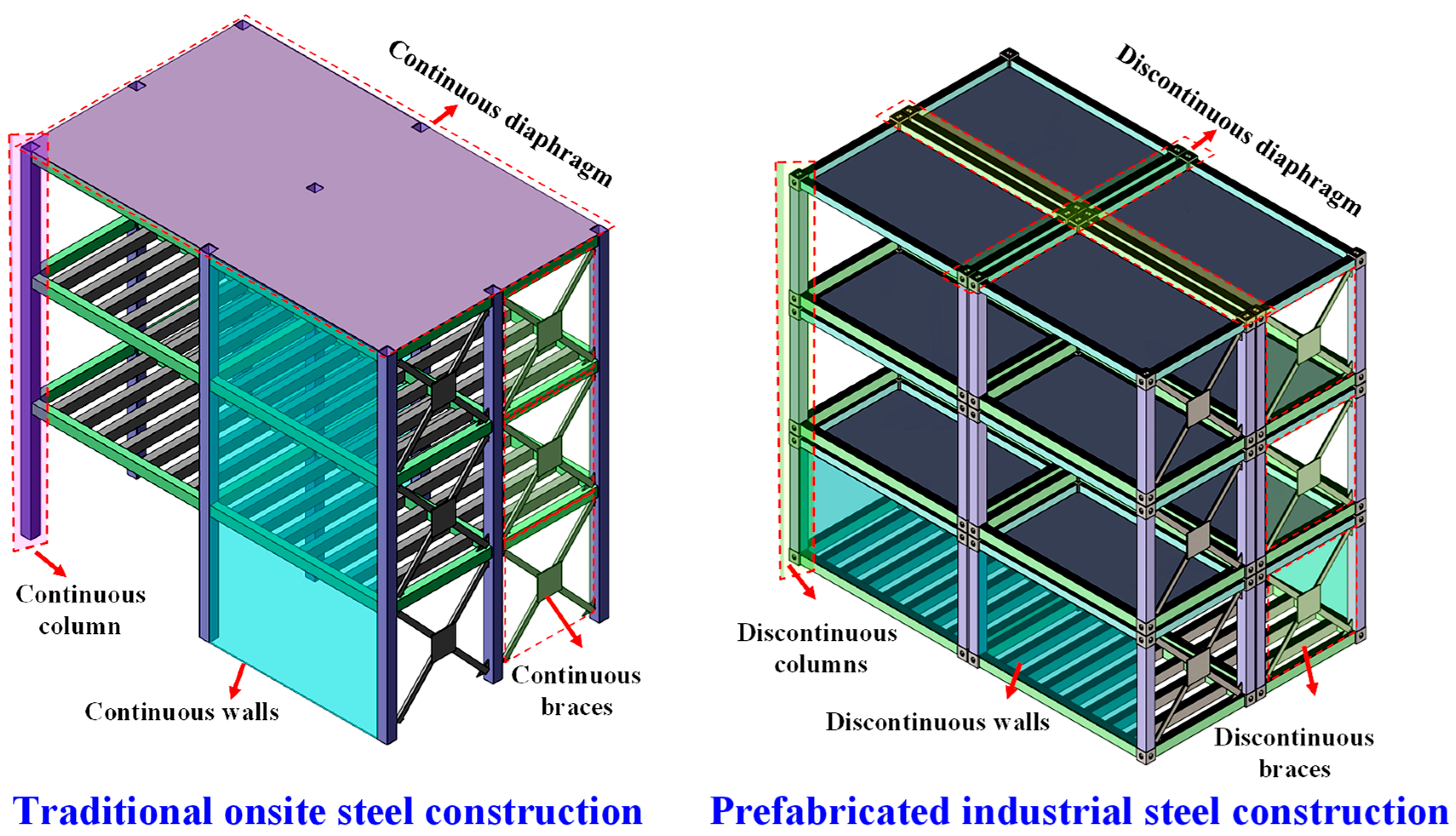
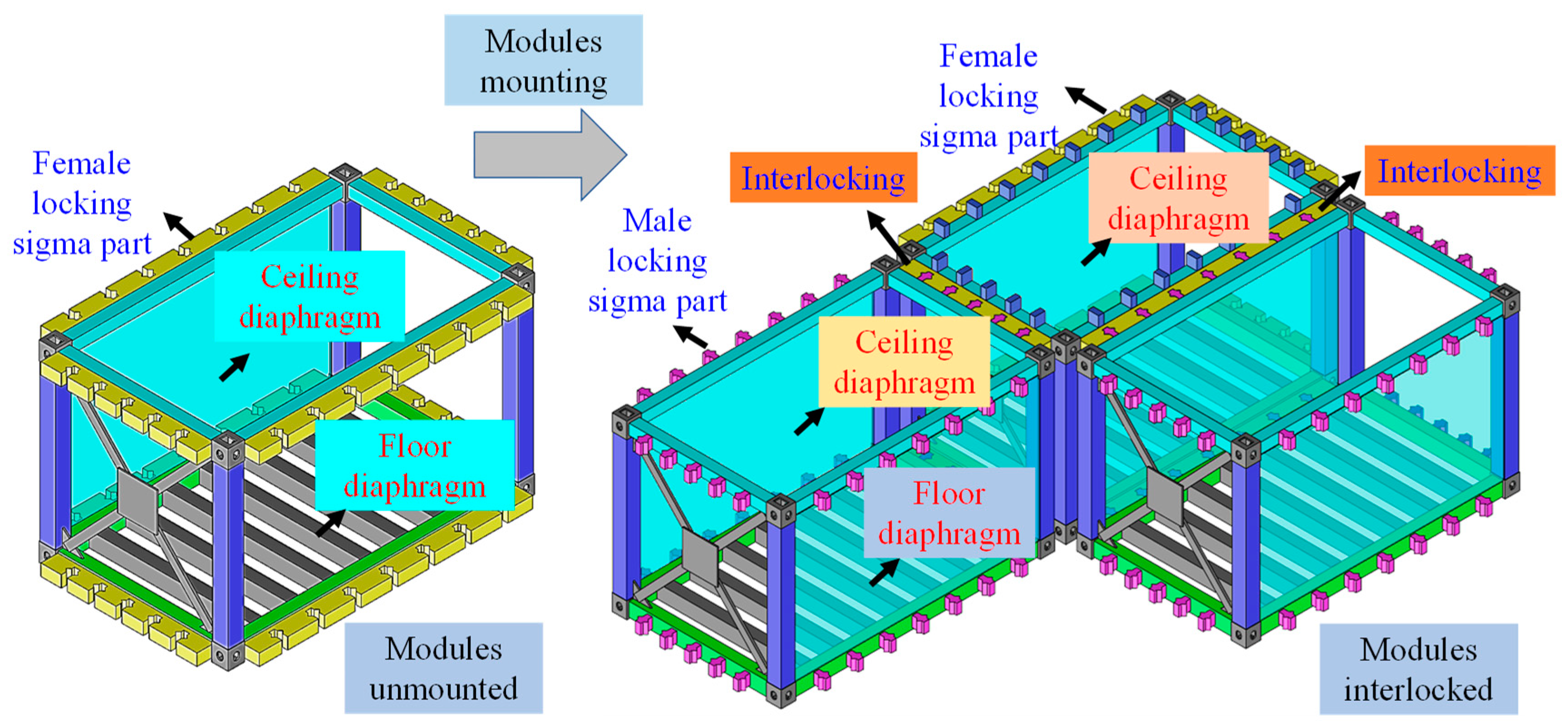
Table 1.
Foundation IMCs and relevant PFISB studies.
| Type | Detailing | Analysis | Features |
|---|---|---|---|
| Anchor IMC [10] |  | No reported studies on structural behavior evaluation | Suitable for high-rise PFISBs, with the ability to withstand uplift, shear stress, and moment owing to anchors cast onsite and welded to the base plate. |
| Anchor IMC [105] |  | No reported studies on structural behavior evaluation | The anchor and plate can be welded to the rubber-pad footing and are suited for the low- to mid-rise PFISBs because it resists uplift, shear stress, and moment. |
| Key IMC [105] |  | No reported studies on structural behavior evaluation | Shear-key in the IMU can withstand shear force and a small moment but is dangerous when subjected to uplifting forces and is not suitable for high-rise PFISBs. |
| Anchor IMC [106] |  | No reported studies on structural behavior evaluation | To resist uplift, shear force, and moment in high-rise PFISBs, the base plate is welded to the connecting plate that has been anchor-welded. |
| Stud IMC [107] |  |  | It can withstand uplift, shear stress, and moment and prevent uplifting while producing ductile failure, but it can also start brittle failure in high-rise PFISBs with infilled moment-frames. |
| Bolted IMC [60,61,63,108] |  |  | They are effectively used in a five-story PFISB in China, where bolts are tightened onsite using nuts, preventing the IMU from rising and resisting uplift, shear strain, and severe moments. |
| Welded IMC [104] |  | No reported studies on structural behavior evaluation | The onsite welded plate has high stiffness and strength and can resist uplift, shear force, and moment. However, full welding is difficult; thus, best suited for mid-rise PFISBs. |
| Key IMC [109] |  | No reported studies on structural behavior evaluation | Although onsite anchors are cast with shear keys and connecting plates, they can resist uplift, shear force, and moment; interior bolting presents a barrier. |
Disclaimer/Publisher’s Note: The statements, opinions and data contained in all publications are solely those of the individual author(s) and contributor(s) and not of MDPI and/or the editor(s). MDPI and/or the editor(s) disclaim responsibility for any injury to people or property resulting from any ideas, methods, instructions or products referred to in the content. |
© 2023 by the authors. Licensee MDPI, Basel, Switzerland. This article is an open access article distributed under the terms and conditions of the Creative Commons Attribution (CC BY) license (https://creativecommons.org/licenses/by/4.0/).
Share and Cite
MDPI and ACS Style
Khan, K.; Chen, Z.; Liu, J.; Javed, K. State-of-the-Art on Technological Developments and Adaptability of Prefabricated Industrial Steel Buildings. Appl. Sci. 2023, 13, 685. https://doi.org/10.3390/app13020685
AMA Style
Khan K, Chen Z, Liu J, Javed K. State-of-the-Art on Technological Developments and Adaptability of Prefabricated Industrial Steel Buildings. Applied Sciences. 2023; 13(2):685. https://doi.org/10.3390/app13020685
Chicago/Turabian StyleKhan, Kashan, Zhihua Chen, Jiadi Liu, and Khadija Javed. 2023. "State-of-the-Art on Technological Developments and Adaptability of Prefabricated Industrial Steel Buildings" Applied Sciences 13, no. 2: 685. https://doi.org/10.3390/app13020685
Note that from the first issue of 2016, this journal uses article numbers instead of page numbers. See further details here.